
INSTRUMENTS > FAQ > GL7000
MAIN BODY
Q1: What is the maximum number of amp unit that can be installed?
A1: Maximum number of units is 10. SSD unit, display unit and alarm unit on the main body are not included in the 10 units.
Q2: What is the maximum number of channels that can be measured with one unit of GL7000 and what is the combination?
A2: The maximum number of channel is 112.
Example 1: Voltage/Temperature unit- 8 units(80 channels) + Logic/Pulse unit-2units (1 unit 32 channels)
Example 2: Logic/Pulse Amp units-7 units (112 channels)
Q3: How to connect mutliple GL7000?
A3: Using standard enclosed software GL-Connection, via LAN/USB hub, maximum of 10 units (112 channels) can be connected.
Q4: Is there a set order of installation to adding amp unit to the main body?
A4: Amp units can be installed between main unit and alarm output unit in any order. With an exception of SSD unit (option), which must be installed next to the main unit.
Q5: What is the difference between internal RAM and internal flash memory?
A5: Internal RAM can record with maximum sampling speed of 1MS/s(1us). The memory is not saved and will erase when power is turned off. If automatic backup function is used, the recorded memory can save in internal flash memory, SD card or SSD(option). Internal flash memory can record with maximum sampling speed of 1kS/s (1ms). The memory is saved in the event of power cut off. (When recording with CSV, sampling speed is 1ms/1ch)
Q6: What will happen to data being recorded when internal RAM or Flash Memory is full?
A6: Recording will end when available memory is exhausted. To continue recording, backup memory to external device and delete from GL7000.
Q7: What is the benefit of using SSD unit?
A7: SSD is high on vibration resistance and has fast access speed. SSD unit (GL7-SSD) can sample at maximum spped of 1MS/s(1us) and record direct to SSD. (Amp unit at 1 to 2 unit)
Q8: How long canSSD unit (GL7-SSD) record?
A8: SSD unit (GL7-SSD) has memory space of 64GB. Each file has up to 2GB. Large volume of recorded data can be stored multiple times. See unit table for detail of recording time.
Q9: Is there a limitation when SSD unit is selected as recording destination?
A9: There is a limitation depending on how many amp units are used. When amp unit is connected but not recording, it is not counted in total unit.
1 ~ 2 units: Maximum sampling speed is 1MS/s (1us)
3 ~ 4 units: Maximum sampling speed is 500kS/s (2us)
5 ~ 10 units: Maximum sampling speed is 200kS/s (5 us)
Sampling speed will depend on amp unit used. The speed will be limited by the fastest amp unit used. When sampling speed is set for each amp unit above the capacity of amp unit sampling speed. The sampling will be done at the maximum sampling speed of each unit and data will be same. When recording destination is selected to SSD unit and recording high voltage unit, logic and pulse unit will have limitations below.
Example 1: Total unit/ 2 units (high voltate unit x 1 unit, logic/pulse unit x 1 unit)
When logic/pulse unit is set at pulse, possible pulse recording channel will change from 16 to 8 channels.
Example 2: Total unit/ 3 units ( High voltage unit x 1 unit, logic/pulse unit x 2 units)
When logic/pulse unit is set at pulse, possible pulse recording channel will change from 32 to 16 channels.
As total recording is with 3 units destined to SSD unit, The maximum high voltage sampling spped is 500kS/s (2us).
Q 10: What are the details to look for in choosing SD cards and which class of speed should be selected?
A 10: The SD card slot for GL7000 will accommodate SD and SDHC but not SDXC. When selecting SD speed calss for GL7000, Class 4 or above should be chosen. Below are list of SE card tested ad used.
| No. | SD-CARD Model | Maker | Remark |
|---|---|---|---|
| 1 | MF-FSDH08GC10R | ELECOM | 8GB-CLASS10 |
| 2 | RP-SDWA08GJK | PANASONIC | 8GB-CLASS10 |
| 3 | RSDC-8GC10B | BUFFALO | 8GB-CLASS10 |
| 4 | SD-K32GR7AR30 | TOSHIBA | 32GB CLASS10 |
| 5 | TS16GSDUI | TRANSEND | 16GB-CLASS10 |
| 6 | TS32GSDHC10U1 | TRANSEND | 32GB-CLASS10 |
Q 11: How long can 32GB SD card record?
A 11: Recording time will depend on the amp unit used and the sampling interval. For detail recording time, see unit table. SD card slot supports SDHV and supports SD card under 32 GB, but as one recording file takes up 2GB, memory card with larger capacity is convenient in recording mutiple times.
Q 12: What is the alarm terminal output specification?
A 12: Alarm output: 10 ch
Output format: Open collector output (pull-up resistor 10kohm)
Maximum rating of output transistor:Collector-GND voltage 501V, collector current 2.0A, collector loss 0.6W.
Q 13: Which cable should be connected to the remote terminal located at the bottom of the main unit?
A 13: Use L input/output cable (model: B-513)
Q 14: Is it possible to calculate channel between GL7000-1 and GL7000-2 when connecting mutiple GL7000 via LAN/USB hub?
A 14: When connecting multiple GL7000 via LAN / USB hub, calculation between CH of GL 7000 1 and GL 7000 2 can not be performed. The calculation on GL-Connection (application software) is statistical calculation.
Q 15: There are two types of trigger functions, Level and edge. What is the difference?
A 15: For the level operation, the input signal is determined at above or below the set value. In edge operation, a trigger is established when the input signal crosses the trigger set value.
Q 16: What is GBD file?
A 16: Graphtec Binary Data Extension, which is the binary data format of Graphtec instrument. Payback is possible only using our compatible equipment and software.
Q 17: What accessory are included the main unit?
A 17: The main unit (including alarm output unit) cover, CD-ROM (instruction manual-GL-connection (PC application software)), AC power cord, 2P-3P conversion adapter, quick start guide, warranty card are included.
Q 18: Can GL7000 be set up to control and transfer data from PC without using included application software?
A 18: Yes, when connecting with USB cable and by starting the unit as the USB drive mode, the data from internal flash memory can transfer to the PC. When connecting with ethernet, by using Web server and FTP function, the setting, control and data transfer are possible.
Q 19: When using PC connection and power is turned off and immediately turned back on, does the PC not recognize the GL7000 in normal state.
A 19: When turning on the PC again, allow at least 10 seconds in between. Not given enough interval may not allow PC to connect properly.
AMP
Q1: What is the maximum number of amp units that can be mounted?
A1: Maximum 10 units can be mounted. SSD unit, display unit and alarm output unit are not included in the 10 units.
Q2: What is the maximum number of channel than can measured with 1 unit of GL7000? With what combination?
A2: Maximum number of channel is 112. The maximum number of channel is 112.
Example 1: Voltage/Temperature unit- 8 units(80 channels) + Logic/Pulse unit-2units (1 unit 32 channels)
Example 2: Logic/Pulse Amp units-7 units (112 channels)
Q3: When connecting to main unit, can different types of amp units be mounted?
A3: Yes, different types can be mounted, as long as the toal channels do not exceed 112.
Q4: Is there a set order of installation to adding amp unit to the main body?
A4: Amp units must be installed between main unit and alarm output unit in any order. With an exception of SSD unit (option), which must be installed next to the main unit. With SSD unit in place, other amps must be mounted in between SSD unit and Alarm output unit.
Q5: What is the maximum sampling speed when different amp units are mounted?
A5: Even with combination of different amp type mounted, each amp unit can be set to maximum speed. However, With exception of Voltage and Voltage/Temperature amp units, there are limitation depending on the recording destination. Please refer to sampling conversion table. If a sampling interval exceeding the maximum speed of the amplifier unit is set while different types of amplifier units are installed, it will be sampled at the highest speed of that amplifier unit, and the same data will be obtained during that interval.
Q6: There are "insulation" and "non-insulation" in the measurement terminal method, but what is the difference between the respective methods?
A6: The insulation has the grounds of each channel that are completely independent. Also referred to as earth floating, voltage measurement at any place is possible. On the other hand, non-insulation shares the same ground for each channel. Only voltage measurement from the common ground can be done.
Q7: What is the best way to take stable measurements with voltage/temperature unit?
A7: Allow the unit to warm up for 30 minutes after unit is turned on for optimum result. Also, by setting sampling interval to 100ms or more (slow), The temperature drift to zero point becomes smaller.
Q8: What is logic/pulse used to measure.
A8: Measure the timing of the control device system with a logic signal, and measure the rotation number and flow rate with a pulse signal.
Q9: Which cable should be connected to the logic/pulse unit?
A9: Use the probe for the logic / pulse unit (model number: RIC - 10). As one cable can input four channels, use 4 cables when all 16 channels are used.
Q10: Does the internal RAM data from Amplifier Unit disappear when power is turned off?
A10: When power is turned off, the data disappears. Use the auto save function to back up data to the internal flash memory, SD card or SSD (option).
Q11: Is there any restriction on using the SSD unit as the recording destination?
A11: There is a limit depending on the total number of amplifier units to use. Even if the amp unit is connected to the main unit, if it is not measuring, it will not be counted in the total number of amplifier units.
For 1 to 2 units: Maximum sampling interval is 1 MS / s (1 μs)
For 3 to 4 units: Max sampling interval 500 kS / s (2 μs)
For 5 to 10 units: Maximum sampling interval is 200 kS / s (5 μs)
The sampling interval is limited depending on the amplifier unit to be used. It is limited to the fastest amplifier unit within the mounted units. When sampling intervals exceeding the maximum speed are set for each amplifier unit, sampling is performed at the highest speed of each unit, and the same data is obtained during that interval. Also, the following restrictions apply when selecting the recording destination as the SSD unit and measuring using the high-speed voltage unit and the logic/pulse unit.
Example 1: Total number of units: 2 units (high-speed voltage unit × 1 unit, logic / pulse unit × 1 unit)
When the logic / pulse unit is set to pulse, the number of channels that can be measured by pulse measurement is 16 ch to 8 ch.
Example 2: Total number of units: 3 units (high-speed voltage unit × 1 unit, 2 logic pulse units)
When the logic / pulse unit is set to pulse, the number of channels that can be measured by pulse measurement changes from 32 channels to 16 channels. Additionally, since it is recorded on the SSD unit with a total of 3 units, the maximum sampling interval of the high-speed voltage unit is 500 kS / s (2 μs).
Q12: What is the maximum input voltage of the GL 7 - V?
A12: Maximum input voltage
Never input a voltage exceeding the specification even for a moment, the circuit of the input area will be damaged.
Avoid static electricity near the analog signal input terminal

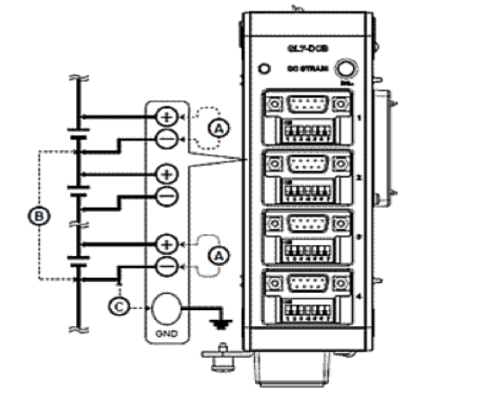
<Between input terminal (+) / input terminal (-) (part A in the figure below)>
Maximum input voltage : 100 mV to 1 V range 60 Vp-p, : 2V to 100V range 100Vp-p
<Between input terminal (-) / input terminal (-) (part B in the figure below)>
Maximum input voltage: 60 Vp-p, Withstand voltage: 1000 Vp-p / 1 min
<Between the input terminal (-) / GND terminal (part C in the figure below)>
Maximum input voltage: 60 Vp-p, Withstand voltage: 1000 Vp-p / 1 mi
Q13: What is the maximum input voltage of the high-speed voltage unit GL 7 - HSV?
A13: Never input a voltage exceeding the specification even for a moment, the circuit of the input area will be damaged.Avoid static electricity near the analog signal input terminal.

<Between input terminal (+) / input terminal (-) (part A in the figure below)>
Maximum input voltage: 100 mV to 1 V range 60 Vp-p, : 2V to 100V range 100Vp-p
<Between input terminal (-) / input terminal (-) (part B in the figure below)>
Maximum input voltage: 60 Vp-p, Withstand voltage: 1000 Vp-p / 1 min
<Between the input terminal (-) / GND terminal (part C in the figure below)>
Maximum input voltage: 60 Vp-p, Withstand voltage: 1000 Vp-p / 1 min
Q14: What is the maximum input voltage of the voltage / temperature unit GL 7 - M?
A14: Never input a voltage exceeding the specification even for a moment, the circuit of the input area will be damaged. Avoid static electricity near the analog signal input terminal.

<Between input terminal (+) / input terminal (-) (part A in the figure below)>
Maximum input voltage: 60 Vp-p
<Between input terminal (-) / input terminal (-) (part B in the figure below)>
Maximum input voltage: 60 Vp-p, Withstand voltage: 350 V pp / 1 min
<Between input terminal and GND terminal (part C in the figure below)>
Maximum input voltage: 60 Vp-p, Withstand voltage: 350 V pp / 1 min
Q15: What is the maximum input voltage of the high voltage unit GL 7 - HV?
A15: Never input a voltage exceeding the specification even for a moment, the circuit of the input area will be damaged. Avoid static electricity near the analog signal input terminal.

<Between input terminal (+) / input terminal (-) (part A in the figure below)>
Maximum input voltage: 1000 Vp-p
<Between input terminal (-) / input terminal (-) (part B in the figure below)>
Maximum input voltage: 300 VACrms, Withstand voltage: 2300 VACrms / 1 min
<Between the input terminal (-) / GND terminal (part C in the figure below)>
Maximum input voltage: 300 VACrms, Withstand voltage: 2300 VACrms / 1 min
Q16: What is the maximum input voltage of the strain unit GL 7 - DCB?
A16: Never input a voltage exceeding the specification even for a moment, the circuit of the input area will be damaged. Avoid static electricity near the analog signal input terminal.
<Between input terminal (+) / input terminal (-) (part A in the figure below)>
Maximum input voltage: DC 10 Vp-p
<Between input terminal (-) / input terminal (-) (part B in the figure below)>
Maximum input voltage: 10 Vp-p
<Between the input terminal (-) / GND terminal (part C in the figure below)>
Maximum input voltage: 60 Vp-p, Withstand voltage: 1000 Vp-p / 1 min
Q17: What is the maximum input voltage of the acceleration unit GL 7 - CHA?
A17: Never input a voltage exceeding the specification even for a moment, the circuit of the input area will be damaged. Avoid static electricity near the analog signal input terminal.

<Between input terminal (+) / input terminal (-) (part A in the figure below)>
Maximum input voltage: 25 Vp-p, Maximum charge input: 50000 pC
<Between input terminal (-) / input terminal (-) (part B in the figure below)>
Maximum input voltage: 25 Vp-p, Withstand voltage: 300 V pp / 1 min
<Between the input terminal (-) / GND terminal (part C in the figure below)>
Maximum input voltage: 25 Vp-p, Withstand voltage: 300 V pp / 1 min
Caution: When connecting voltage signal, input setting must not be built into amp. Since Voltage will be output from BNC connector, it may cause damage to measurement tool and the main unit.
Q18: How many Logic/Pulse Unit of GL 7 - L / P can be connected to the main unit?
A18: Logic pulse unit switches logic/pulse for each unit. Up to 7 units (112 ch) can use the logic function. Up to 2 units (32 ch) can use the pulse function. In addition, the connection of each amplifier unit to the main unit is up to 10 units (maximum 112 ch).
Q19: How many strain unit (GL 7 - DCB) can be connected to the main unit?
A19: The maximum number of strain units that can be installed on the main unit is 8. When more than 8 units are connected, a message will display at power on and access will not be available. Also, up to 10 units can be used with 8 units of GL7-DCB combined with other units.
Q20: What kind os sensor can connect with the strain unit GL7-DCB?
A20: Strain gage and strain gage applied transducer are connected. There are the following types of strain gage applied transducers.
| Strain Gage type converter/Sensor Type | Detail |
|---|---|
| Acceleration sensor | Acceleration during running, mechanical vibration and etc. |
| Load cell (load transducer) | Tensile tester, industrial scale, weight scale and etc. |
| Pressure transducer | Gas pressure (air, gas, etc.) Liquid pressure (water, oil, etc.) |
| Pressure transducer | Gas pressure (air, gas, etc.) Liquid pressure (water, oil, etc.) |
| Torque transducer | Torque of drive unit as engine and motor |
To connect with strain unit, connect according to the output shape of the sensor as DSUB connector, theDSUB-NDIS conversion cable (B-561), or the DSUB-screw terminal conversion connecor (B-560). B-560, B-561 is sold separately and available to purchase as needed and can be attached to the strain unit at the same time. (Example: B-560 is attached to 1ch and 2ch, B-561 is attached to 3ch and 4ch etc.)
Q20: How many acceleration units, GL7-CHA can be connected to the main unit?
A20: The maximum number of acceleration unit that can mount on the main unit is 10.
Q21: which sensor can connect with acceleration unit GL&-CHA
A21: Acceleration unit (GL7-CHA) can connect with piezoelectric acceleration and with various other piezoelectric sensors. Piezoelectric sensors have charge type and built-in amplifier type, both measured by setting sensor sensitivity.

Q22: How to connect strain unit GL7-DCB to sensor with NDIS connector?
A22: When connecting a sensor with an NDIS connector, connect by using the optional DSUB - NDIS conversion cable (B - 561). The DSUB - NDIS conversion cable B - 561 is sold individually. Purchase channels as needed.
Q23: Is the optional DSUB - screw terminal conversion connector B - 560 comes in 4 sets?
A23: The DSUB - screw terminal conversion connector B - 560 is sold individually. Purchase as needed.
Q24: What standard conforms to the TEDS function?
A24: The strain unit GL 7 - DCB corresponds to the IEEE 1451.4 standard template No. 33 strain sensor. The acceleration unit GL 7 - CHA corresponds to the IEEE 1451.4 standard template No. 25 acceleration sensor.
Q25: L7 - DCB strain unit is attached, but the amplifier unit is not recognized from the display unit of the main body and on the GL - Connection application software.
A25: When using GL7-DCB strain unit, set the firmware version of the main unit to Ver 1.20 or more. In addition, the application software GL-Connection must be Ver 1.20 or higher. To download the firmware and software update version, please do from the GL 7000 related download.
Q26: How to measure strain using GL 7 - DCB strain unit, and how to connect to the sensor.
A26: Please refer to the following documents which summarizes the types of sensors, connection method and usage of GL 7 - DCB strain unit.
Click >> Know-ho of strains Click >> Connection method and utilization
Q27: GL 7 - CHA acceleration unit is installed, but amp unit is not recognized from GL-Connection of the main unit display unit or application software.
A27: When using GL 7 - CHA Acceleration Unit, the firmware version of the main unit must be Ver. 1.30 or more. In addition, the application software. GL-Connection must be Ver 1.30 or higher. To download the firmware and software update version, please do from the GL 7000 related download (icon listed above).
Q28: How to connect to the sensor to measure acceleration using GL 7 - CHA acceleration unit.
A28: Please refer to the following documents which summarizes the types of sensors, connection method and usage of GL 7 - DCB strain unit.
Click >> Know-ho of strains Click >> Connection method and utilization
Q29: What does the GL 7 - DCO analog voltage output unit do?
A29: GL7 - DCO Analog voltage output unit is a unit that can accurately output analog voltage data recorded and fake simulation by analog voltage output of arbitrary waveform.
Q30: After installing the GL7-DCO analog voltage output unit amp unit is not recognized from the display unit of the main body and GL - Connection of application software.
A30: When using GL 7 - DCO analog voltage output unit, set the firmware version of the main unit to Ver 1.40 or more. Also, the application software. GL - Connection must be set at Ver. 1.40 or higher. Please update the firmware and software with the CD-ROM included in GL-DCO you purchased, or download from GL 7000 related download from our website.
Q31: What is the fastest sampling rate of GL 7 - DCO analog voltage output unit?
A31: The fastest sampling rate is 100 kS / sec (10 μs).
Q32: What kind of waveform can be set for output with GL 7 - DCO analog voltage output unit?
A32: DC, sine wave, triangle wave, ramp wave, pulse wave can be set for the waveform type. In addition, it can generate arbitrary CSV waveform data with GL-Wave Editor attached to GL-Connection. * Microsoft EXCEL (Office 2003 or later) is required.
Q33: What is the voltage and current that can be output from GL 7 - DCO analog voltage output unit?
A33: The voltage amplitude that can be output is 0 to 20 V (it may vary from -10 V to +10 V depending on the offset) Output current is ± 10 mA / CH (allowable load resistance: 1 kΩ or more, output impedance: 1 Ω or less). However, the total output current of one unit is within ± 40 mA.
Q34: Can I synchronize the output of the waveform with the start key of data recording?
A34: Waveform output from GL - DCO can be synchronized with start key by setting. By default, it is asynchronous, it can start outputting by pressing the output start icon. This operation can be performed during data acquisition or while data acquisition is at a holt.
Q35: I would like to measure the strain using L7 - DCB strain unit, but what voltage is appropriate for the voltage applied to the strain gauge?
A35: The GL7 - DCB unit can set the bridge voltage from 1 · 2 · 2.5 · 5 · 10 V. The initial value of the bridge voltage is 1 V. (Initial value will be 2 V from Ver.1.41 onwards.) In order to measure with stability, the bridge voltage shown in the table below is recommended. However, if heat radiation is attached to a material with poor heat dissipation, lower the bridge voltage.

Q36: How to measure the strain using GL 7 - DCB strain unit, and what voltage is appropriate for the voltage applied to the strain sensor?
A36: The GL7 - DCB unit can set the bridge voltage from 1 · 2 · 2.5 · 5 · 10 V. The initial value of the bridge voltage is 1 V. (Initial value will be 2 V after Ver. 1.41.) For stable measurement, confirm the recommended applied voltage described in the specifications of the sensor to be used, set the voltage as close to the upper limit as possible. However, please be careful not to exceed the upper limit value. <Setting example> When "Recommended applied voltage 1 to 2 V" is noted, set the bridge voltage to 2 V. When "Recommended applied voltage 1 to 7 V" is noted, set the bridge voltage to 5 V.
Q37: Although it is measured with a strain sensor using GL 7 - DCB strain unit, data fluctuates due to the influence of external noise. Is there a countermeasure method?
A37: If the measured value fluctuates due to external noise, we recommend the following countermeasures. (The effect varies depending on the type of noise.)
Ground the GL 7000 main unit to earth.
Please set the bridge voltage to the appropriate value. (Q: Please refer to "What voltage is appropriate for the voltage applied to the strain sensor?")
The following low pass filter can be set for each CH. Line (1.5 Hz) · 3 · 6 · 10 · 30 · 50 · 60 · 100 · 300 · 500 Hz, 1 · 3 · 5 · 10 kHz Since this low pass filter is a fifth order filter, it has sharp attenuation characteristics which is effective in removing noise. Please set the filter value according to the noise frequency.
Q38: What is the temperature that can be measured with K type and T type thermocouple?
A38: It depends on the corresponding temperature range of the thermocouple used. Measurement temperature setting on the main unit side is as follows.
Measurement range setting K type thermocouple is -200 ℃ ~ + 1370 ℃
Measurement range setting T type thermocouple is -200 ° C to + 400 ° C
* The actual measurement temperature range varies depending on the thermocouple used. Please use thermocouples that match the temperature range and environment to be measured, including commercially available products. Our thermocouple specification (K type / T type)

DISPLAY UNIT
Q1: What is the maximum number of waveforms that can be displayed on the display unit?
A1: Waveform display of 112 ch is possible.
Q2: How to lengthen the connection cable between the display unit and the main unit.
A2: A 40 cm connection cable is attached to the display unit, but it can extended up to 10 m using a commercially available LAN cable (CAT 5 or more). Avoid using cross cable and use a straight cable. The cable between the display unit and the main unit is diverted to the LAN cable, but it is not for connecting to the LAN. When connected to main unit LAN connector, display unit will not display nor allow access to HUB.
Q3: What is free running?
A3: A function to display the state of the input signal without recording.
Q4: There are two types of trigger functions, Level and edge. What is the difference?
A4: For the level operation, the input signal is determined at above or below the set value. In edge operation, a trigger is established when the input signal crosses the trigger set value.
Q5: How to record data but erase the waveform display.
A5: With the trace function, set the waveform display On / Off.
Q6: Is it possible to change the display language to be used overseas?
A6: Select and change the display in 6 different languages, Japanese, English, French, German, Chinese and Korean.
Q7: How long is the life of the touch panel?
A7: The reference lifetime of value is about 50,000,000 times. However, it is not a guaranteed value as it depends on the usage and other variables.
Q8: How long is the lifetime of the backlight of the display unit?
A8: As a reference value of backlight lifetime, it is about 50,000 hours (brightness is reduced to 40%) under the condition of use environment temperature 25 ℃. However, it is not a guaranteed value as it varies according to the usage environment.
Q9: Can the display unit be battery operated?
A9: Display unit can not be operated by battery. The display unit connects to the main unit and operates with power from the main unit side. AC power supply is necessary for the main unit, and it is not for DC drive (battery driven).
Q10: When display unit was connected to main unit via LAN cable, nothing showed on screen?
A10: Check the possible causes below,
1. Is the LAN cable straight?
Is the length of the LAN cable 10 m or less?
LAN cable used must be straight (CAT 5 or higher) only. Cross cable can not be used. The length of usable LAN cable. (CAT 5 or more) is within 10 m.【Connection example 1 (normal connection)】

LAN Cable (Straight Max. 10m, above CAT5)
CAUTION: DO NOT USE CROSS CABLE
2. Is hub (HUB) being used?
Although the display unit connection cable uses the LAN cable, it can not be used as a hub (HUB) as it does not.【Connection example 2 (connection not possible)
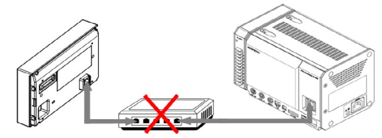
CAUTION: DO NOT USE CROSS CABLE
3. Is the display unit connected to the PC LAN connector AT the bottom of the GL 7000 main unit?
The PC LAN connector at the bottom of the GL7000 main unit is for connecting the PC and the GL 7000 main unit Do not connect the LAN cable from the display unit to the LAN connector of the PC I / F on the GL7000 main unit.
【Connection example -3 (connection not possible)】

CAUTION: DO NOT CONNECT DISPLAY UNITWITH GL7000 PC I/F MAIN UNIT LAN CONNECTOR USING LAN CABLE
Q11: If the power is turned on immediately after turning off the power, the screen will not display properly.
A11: When turning the power on again after turning off the power, wait at least 10 seconds.
If you do not leave an interval, the main unit display may not function or start properly.
SOFTWARE
Q1: Supported OS.
A1: Supports:Windows 10 (32/64 bit), Windows 8.1 (32/64 bit), Windows 8 (32/64 bit)
Does not support: Windows 7 (32/64 bit) Starter Edition
* Graphtec does not support OS that are no longer supported by OS makers.
Q2: How many channels of waveforms can the GL - Connection screen display?
A2: The GL-Connection is multi-window, and one screen can display the waveform for 112 channels. Waveform
Q3: Connecting multiple GL 7000.
A3: Up to 10 units (up to 1120 ch) of FL7000 can be connected via LAN / USB hub using GL-Connection of standard attached software.
Q4: How to synchronize and record using multiple units of GL7000?
A4: By connecting the synchronization cable B - 559 to the synchronous IN / synchronous OUT terminal of the GL 7000 Complete synchronization can be achieved via PC using up to five units of GL7000.
Q5: How to erase the waveform display while recording data.
A5: Waveform display can be turned on or off by use of trace function.
Q6: How to record data only on the PC without recording on the GL 7000 main unit?
A6: Record by setting the data recording destination of GL-Connection.
Q7: While connecting multiple units of GL7000 via a LAN / USB hub, can it calculate CH between GL 7000- 1 and GL 7000- 2?
A7: With multiple GL7000 are connected via LAN / USB hub, calculation between CH of GL-7000 1 and GL-7000 2 is not The calculation on GL-Connection (application software) is statistical calculation. Calculation between channels is within the GL7000 main unit.
Q8: What is free running?
A8: It is a function to display the state of the input signal without recording.
Q9: What is a GBD file?
A9: Graphtec Binary Data extension, which is the binary data format of our instrument. Playback is possible with our compatible equipment and software.
Q10: Can you control your GL7000 and transfer data from the GL7000 from PC without using standard attached dedicated PC application software?
A10: When connected with the USB cable, the data can transfer from the GL 7000 internal flash memory to the PC by using the GL 7000 main unit as the USB drive mode. Also, when connecting to the Ethernet, you can set up, control and acquire data from Internet Explorer using the WEB server function and FTP function.
Q11: Can other midi LOGGER series be used with GL 7000 through standard included software GL - Connection?
A11: There is a plan to upgrade GL-Connection after December 2012. After upgrading, you can connect GL 900-4 / GL 900 - 8 / GL 820 / GL 220 with GL - Connection.
Q12: There are two types of trigger functions, Level and edge. What is the difference?\
A12: For the level operation, the input signal is determined at above or below the set value. In edge operation, a trigger is established when the input signal crosses the trigger set value.
Q13: Is it possible to change the display language to be used overseas?
A13: Select and change the display in 6 languages, Japanese, English, French, German, Chinese and Korean.
Q14: Is there any restriction on using the SSD unit as the recording destination?
A14: There is a limit depending on the total number of amplifier used.
If an amp unit is connected to the main unit, but is not measuring, it is not be counted in the total number of amplifier 1 to 2 units: maximum sampling interval is 1 MS / s (1 μs)
For 3 to 4 units: Max sampling interval 500 kS / s (2 μs)
For 5 to 10 units: Max sampling interval is 200 kS / s (5 μs).
The sampling interval is limited depending on the amplifier unit used. It is limited to the fastest amplifier unit in the When sampling intervals exceeding the maximum speed are set for each amplifier unit, sampling is performed at and the same data is obtained during that interval.
Also, the following restrictions apply when selecting the recording destination as the SSD unit and measuring using
Example 1)
Total number of units: 2 units (high-speed voltage unit Å~ 1 unit, logic / pulse unit Å~ 1 unit) When the logic/pulse unit is set to pulse, the number of channels that can be measured by pulse measurement change
Example 2)
Total number of units: 3 units (high-speed voltage unit Å~ 1 unit, 2 logic pulse units) When the logic/pulse unit is set to pulse, the number of channels that can be measured by pulse measurement changes As it is recorded on the SSD unit with a total of 3 units, the maximum sampling interval of the high-speed voltage
Q15: GL 7000 analog voltage output unit(GL 7 - DCO was purchased, but the included software "GL - Wave Editor (EXCEL macro)" is not found in the CD.
A15: The file is not visible in CD. When GL-Connection Ver.1.40 or later is installed, it will be installed automatically in the following folders.
*My Documents> Graphtec> GL-Connection> Temp> EXCEL 2007> GL-WaveEditor.xlsm
*My Documents> Graphtec> GL-Connection> Temp> GL-WaveEditor.xls

* When using EXCEL 2007 or later, use GL - WaveEditor.xlsm in the EXCEL 2007 folder, otherwise use GL - WaveEditor.xls in the Temp folder.
* Documents and My Documents folder display may appear depending on the Windows.
OPERATION
Q1: How to copy the data in the internal memory all at once to the PC?
A1: When connecting with the PC via USB, Hold the start/stop button while powering on the unit, this will bring you into It recognizes it as a removable disk and can easily perform file transfer/erase etc. For details of the operation, refer
Q2: How to set it with the Web server function without attaching the display unit. How to set the IP address?
A2: The setting uses the Config program that is included in the installation of GL-Connection.
Start the software by selecting "Start" → "Program (All Programs)" → "Graphtec" → "GL-Connection" → "GL-Config" GL-Config can be controlled only with USB connection.
When the "Load" button is pressed after starting, the information of GL 7000 is displayed on the screen. On the screen under the heading "LAN" allows setting of the IP address.
Q3: While voltage is applied to 1 CH using the voltage/temperature unit GL 7 - M and 2CH is open, 1 CH voltage waveform show out in 2 CH
A3: As the voltage/temperature unit GL 7 - M is a scan type and is operated with a switch, it may affect other open CHs CH which is not used to OFF, or short the +/- of CH which is not used.
Q4: How can I convert the data taken with GBD to CSV by handset operation and export it to SD card?
A4: Convert and save from the data playback screen. The method is as follows.
① After stop recording, go to "Home" ⇒ "Replay" ⇒ "Play" to display the playback screen.
② Select "Home" ⇒ "File" ⇒ "Save Data".
③ Select "<SD> SD card" for "File name" and select "CSV" as file format.
④ The data converted to CSV is written out to the SD card by selecting "naming method" for "automatic", selecting "all data" for "storage range" and "save"
Q5: When reproducing a data taken in the CSV format on the main unit operation, and the message "There is no file" is displayed.
A5: Data taken in CSV format can not be played on the main unit. To play data in CSV format Install GL-Connection of the PC and open it from the application software. or open it in Microsoft Excel.
Q6: What is the resolution of each unit amplifier.
Voltage unit / high-speed voltage unit

Voltage / temperature unit

Voltage

Temperature

※ Pt 1000: IEC 751 compliant
Q7: Temperature is measured with a thermocouple using the voltage/temperature unit GL 7 - M, but it does not stabilize What is the cause?
A7: There is a possibility that it is swinging under the influence of hum noise (noise of commercial power supply 50/60 The voltage/temperature unit GL 7 - M has a function to eliminate noise with a digital filter. However, in cases when the commercial power supply frequency used or the sampling interval is set to less than 500 ms it will not be valid. The setting of the AC line frequency has items of "AC line frequency (GL 7 - M)" in "Home" ⇒ "Main unit setting" Please confirm whether it matches with the commercial power frequency used.
As for sampling interval, there is a [sample interval] within "Home" ⇒ "Main unit setting" ⇒ "Data setting" ⇒ "Recording setting", check to make sure the value is 500 ms or more .
Q8: What is a shunt calibration function?
A8: Shunt calibration function is to correct error of strain gauge.
Incorporating the shunt resistance (about 60 kΩ: when 120 Ω . about 175 kΩ: when350 Ω) and the strain gauge internally (calibration) is automatically performed to reduce error in the measurement range and with increased accuracy.
Q9: What is the function of remote sensing?
A9: The remote sensing function is a function to correct the lead wire resistance. Remote sensing function eliminates conductor resistance change of cable which is an error factor.
Q10: When 1 gauge method, 2 gauge method, 4 gauge method, strain gauge measuring method or connection of strain terminal is made, It supplies a stable voltage eliminating the voltage drop due to the conductor resistance of the Q 10 When setting the sensor type of charge type and built-in amplifier type in the acceleration unit GL 7 - CHA, but not The sensor sensitivity specification is ***** pC / N or ***** mV / g. Can it be set?
A10: It is configurable.
First, set the numerical value of ***** (***** pC / N or ***** mV / g) described in the sensor sensitivity specification unit (GL7 - CHA) In the setting, enter the value as is.
Next, in the scaling setting, keeping the conversion of measured value and the output value at 1: 1, select the unit Q 11
Q11: How to upgrade the firmware when there is no display unit?
A11: The firmware version can be upgraded by the GL 7000 control software "GL-Config" contained in the included CD-one-to-one connection with the USB cable or LAN cable, launch "GL-Config", and click [Firmware Update]. For the application manual "Firmware version upgrade method".
Q12: What happens to the CH display when the amplifier unit is divided into multiple?
A12: When there are two or more amp units, the CH display starts from Unit 1-1, and when it reaches the last CH of Unit In the waveform display, you can select whether to display the waveform with the trace on/off setting
Q13: While using the web server function, the device stops responding.
A13: The Web server function processes according to the demand from the PC browser.
On the "Remote operation" screen and "Screen display" screen, the browser issues a screen data request to the device
of seconds set in the web screen "2 seconds / 5 seconds / 10 seconds". The processing requested by the browser processing is carried out internally.
For this reason, when screen data requests are overlapped inside the device or the line speed is low in the first place, is not completed from the request until the next request, processing is accumulated in the queue, finally, the queue turn off the browser, return short time later and proceed.
After recovery, reset the screen update cycle on the web screen to later period. When a key on the web screen is while demanding data screen. When the key is clicked multiple times, a demand accumulates within the system. then go to the next click.
Q14: Is there a sampling interval restriction at the time of recording, when files are periodically back up?
A14: The backup setting can be used when setting a slow sampling interval with a interval of 1 ms or more. Also, when the destination depends on the recording destination. Please note the following details while setting for backup.
Set the sampling interval to a slow sampling interval of 1 ms or more.
The recording destination and the backup destination cannot be set in the same place.
The backup destination setting is to one place only.
When the recording format is "CSV", the backup function can not be used.
When ring recording is ON, the backup function can not be used.
Q15: How to copy the data saved in the built-in flash memory to the SD card.
A15: For the method of copying data from the built-in flash memory to the SD card, refer to "How to Copy Data to SD Card of GL 7000 (pdf: 112 KB)".
CONNECTING GL7000 TO COMPUTER VIA USB
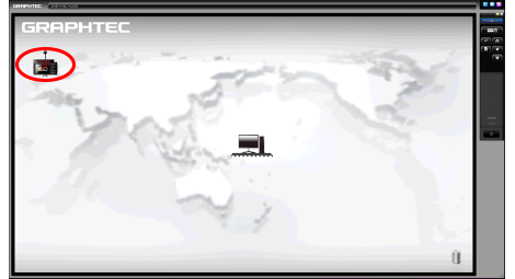
Step 1: Download and install both the USB driver and the APS software from our web site >> Click GL7000 Download
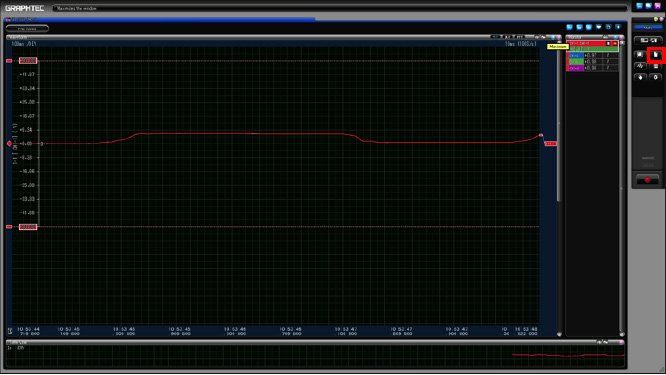
Step 2: Once you have downloaded and installed both items, proceed to opening the GL7000 APS software. You will get this screen once open and you will click on the computer icon (highlighted in Red). This will prompt a signal to come out of the computer and detect the GL you have connected.
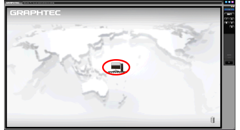
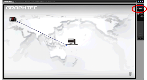
Step 3: You will now get a GL icon that pops up somewhere on the screen of the GL connection software, click on the GL icon and you will see a load bar appear
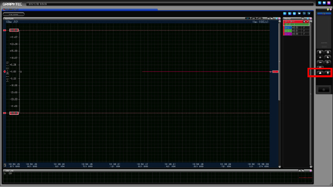
Step 4: You should now see a blue line connecting the GL icon and the Computer icon to each other (as shown in the picture below). Next you will click on the switched screen icon (highlighted in red) and this will take you to the GL connection software with the GL7000 connected.
CONVERTING FILE GBD TO CSV ON GL900
Note: You can only convert from GBD to CSV, not the other way around. So it is best to save in GBD as you can convert to CSV at any time.
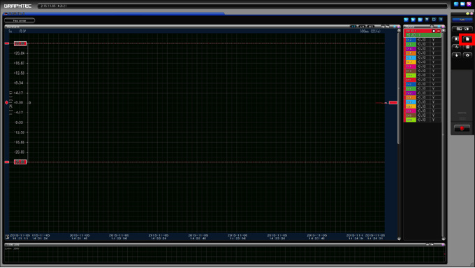
Step 1: Once you have opened the APS and connected the GL, you must press the File button located near the top left of the screen (highlighted in red).
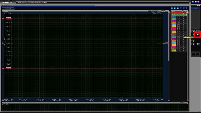
Step 2: After clicking the file option, a new menu will appear and you choose the option CSV file batch conversion (highlighted in red).
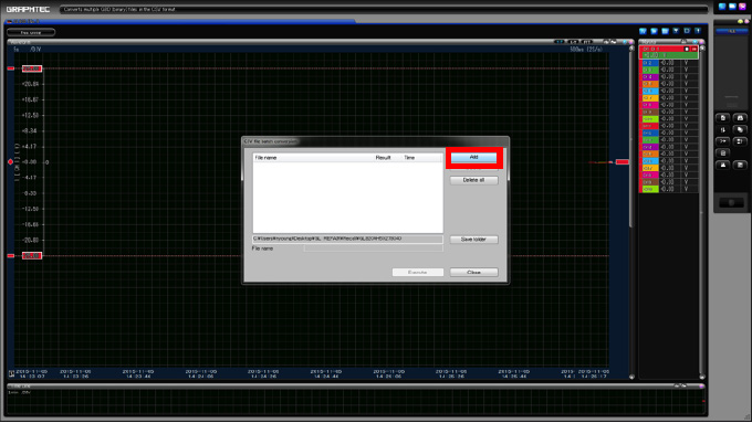
Step 3: A new menu will pop up now that you selected the file option. From here press the add button (highlighted in red). This menu is a batch menu where your added files that you want to convert will show.
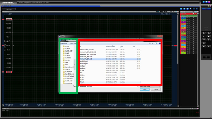
Step 4: When the new window pops up, you will have options on the left hand side on choosing where you are importing the file from (highlighted in green). Your files will appear on the right of where you select the file. Here is where you will see the files that are in the location you are choosing from, this is where you select the file you want (highlighted in red).
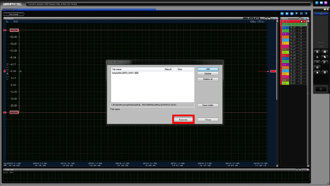
Step 5: After your file is selected, you will see what you chose pop up in the batch menu. From this point, you can either add more files to the batch or you can select execute (highlighted in red), which will convert the file you have selected.
PRINT SCREEN OR SAVE SCREEN DISPLAYS ON GL900
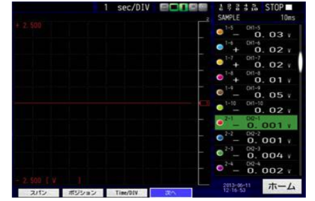
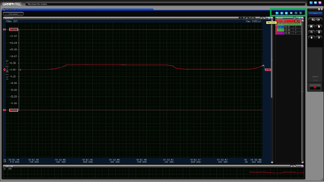
Step 1: After you open the software and connect your GL, you will be at a screen similar to this one. Here your graph will display the signal it in the form of a wave or you can change the display to digital, or just have a report of your information (highlighted in green)
Step 2: To either print or save what you have on the screen (does not matter which screen you’re in), you have to select the file operations option located on the upper left hand side of the screen (highlighted in red)
Step 3: Once you click file operations, you will get a get a new menu. The bottom two options on that new menu (highlighted in red), are to either print (will send screen shot to printer) or to save screen (which will save screen shot) to either internal or external memory.
INSTRUMENTS > FAQ > GL7000