
FAQ > GL100
GL100
Connecting GL100 to GL240 and GL840 > Click here
Setting the sensor module and main unit > Click here
What is the power supply recommendation for the GL100 > Click here
How long will the AA alkaline batteries last while measuring with a temperature / humidity sensor?
How many days can the data be stored in the internal memory?
How many days can you record continuously on 2GB SD card?
What is the operating environment of the main unit?
What is the waterproof and rustproof measure of the main body?
Can I output an alarm signal to an external light or buzzer?
How do I connect the GL100 to the PC?
What are the wireless LAN standards and communication distance of the GL100-WL?
What wireless LAN modes and security setting can be set with the GL100-WL?
What information can I send with GL100-WL?
What is the recommended SD card?
Is it possible to measure both temperature and humidity at the same time?
Is it possible to measure room temperature at multiple places with certain accuracy?
I want to measure pulse, temperature and voltage at the same time, is it possible?
Is it possible to measure AC current and power?
I want to measure temperature, humidity, illuminance levels at the same time, is it possible?
Is it possible to measure temperature, humidity, CO2 levels at the same time?
Is it possible to measure CO2 level and illuminance at the same time?
Is it possible to measure acceleration and temperature at the same time?
I would like to extend the distance from the main unit to the sensor.
What is the max AC current that can be measured?
Is it possible to measure three-phase three-wire system?
What kind of thermocouples can be used with the 4 ch voltage / temperature terminal (GS-4 VT)?
What is the maximum voltage that 4ch voltage / temperature module (GS-4VT) can measure?
What is the range of temperature and humidity for the temperature / humidity sensor (GS-TH)?
What is the resolution and accuracy of humidity and temperature on the GS-TH sensor?
What is the resolution and accuracy of the 4ch thermistor sensor (GS-4TSR)?
What is the fastest sampling rate of three-axis acceleration / temperature sensor (GS-3AT)?
RECORDING TIMES
CONNECTING GL100 TO GL240 AND GL840
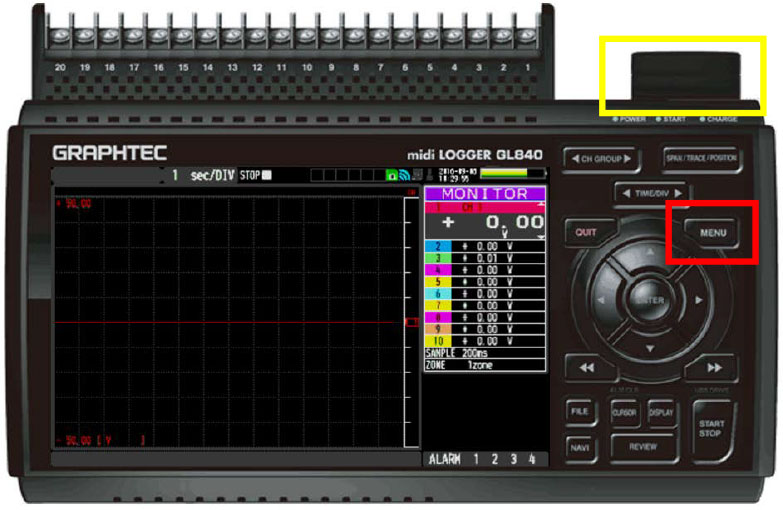
Step 1: Hit Menu.
***Make sure you have Wireless Module Attached. (highlighted in yellow)
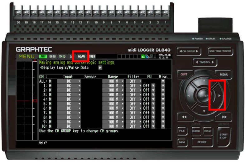
Step 2: Use arrow Key to go to WLAN
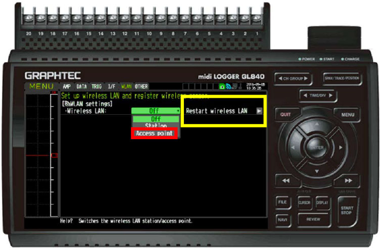
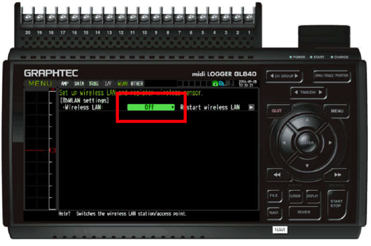
Step 3: Click on highlighted green box to get drop down Menu
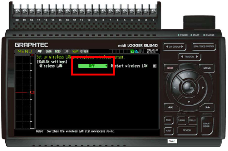
Step 3: Click on highlighted green box to get drop down Menu
Step 4: Select Access Point and hit okay. Then hit the Enter button on the Restart the wireless LAN(highlighted in Yellow) and wait for it to restart.
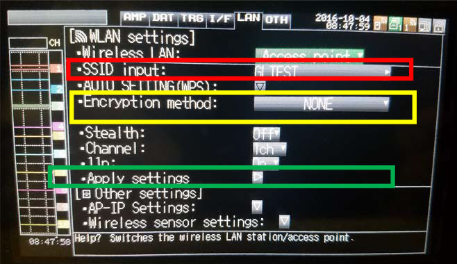
Step 5: Now, you will get a screen similar to the one above. Here is where you set your name and if you want, a password. The SSID Input (highlighted in red) is where you choose the name of the GL240/840 so you can select it from the GL100. Next you will select Encryption method (highlighted in Yellow), which is where you select how secure your password is, this will also bring up an extra column of where you can put in a password.
After these parameters have been set, Hit Apply settings (highlighted in Green) and we are now done with the GL240/840 for now and will now be grabbing the GL100.
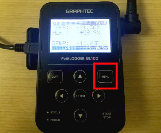
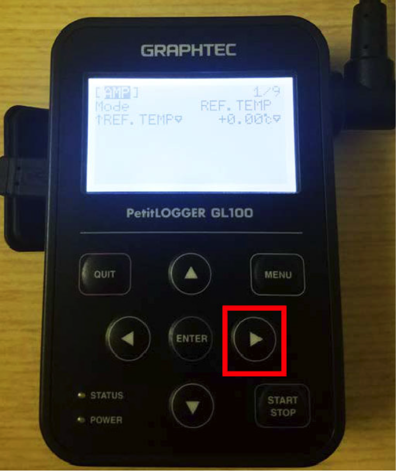
Step 6: Now we are working from the GL100, when powered on, your start screen will look similar to this depending on the sensor connected. From here hit the MENU button highlighted in red.
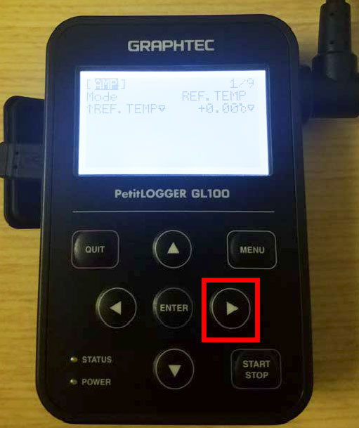
Step 7: Now Hit the Left arrow Key to switch MENUs until you are at the I/F menu.
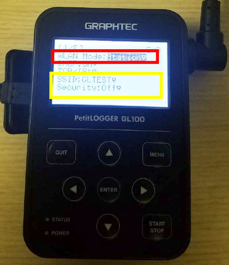
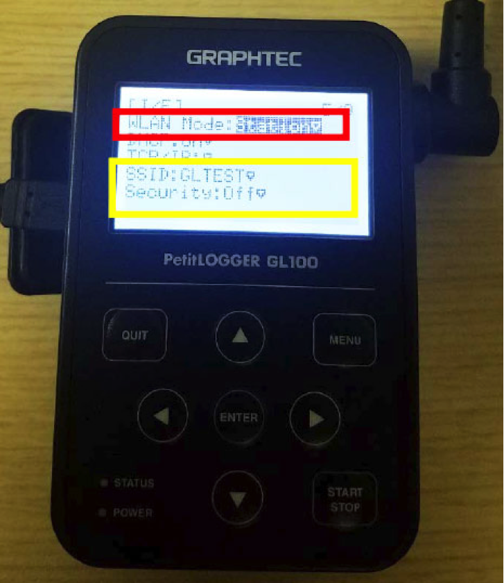
Step 8: You will want to set the WLAN mode (highlighted in red) to Station. Then Set your SSID and Security setting (highlighted in yellow) to the same as you set your GL240/840 too.
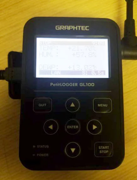
Step 9: After you have set everything up from step 8, press QUIT on your GL100 to return to the main screen. From here you should now see LAN (highlighted in red), this will indicate that you are now connected to the GL240/840. From here we now go back to where we left off on the GL240/840.
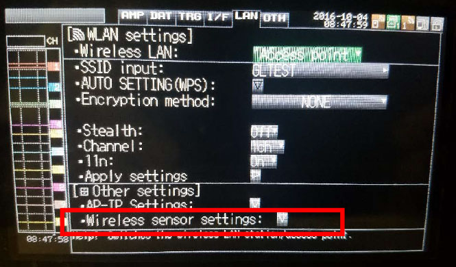
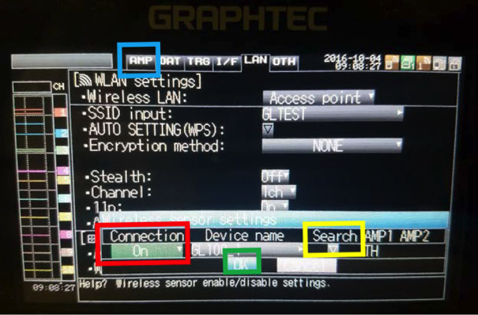
Step 10: Now that you are back to your screen you left off on the GL240/840, go down to the Wireless sensor settings (highlighted in red) and select it to get menu.
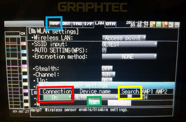
Step 11: From here select connection to On (highlighted in red). Then go over to search (highlighted in yellow) and it will search and find your GL100 sensor, from there select it. Then hit OK (highlighted in green). Now if you go to the AMP (highlighted in Blue) menu there will be one more step.
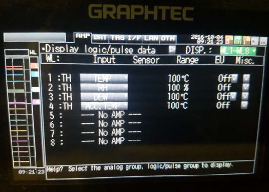
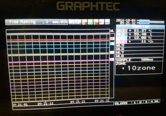
Step 12: Once back to the AMP MENU, you can toggle between displays, if you hit the DISP (highlighted in red) you will get a drop down menu to select. Once selected the input and sensor will change to the GL100. If you hit Quit after selecting you will get the screen similar to the two below.
SETTING THE SENSOR MODULE AND MAIN UNIT
In the case of the temperature and humidity sensor (GS-TH), set the sensor module and the main unit in a way where the sensor faces the upper right corner of the main unit as shown in the figure. For other sensor modules, set so that the cable faces to the lower right portion as the connector fits into the main unit GL100 body.

WHAT IS THE POWER SUPPLY RECOMMENDATION FOR THE GL100?
The power supply is available using either USB bus power from PC, USB AC adapter or two AA alkaline batteries.
※ USB AC adapter: Specifications, 5V 1A, USB bus power: 5V 200mA
※ Battery drive is available only for AA alkaline batteries. Rechargeable batteries cannot be used due to insufficient voltage.
※ CO2 sensor cannot be used with battery drive.
Recommended power supply combined with the specific sensor modules are:
| Setting | Connection module | Alkaline dry battery | USB power supply |
|---|---|---|---|
| Temperature / humidity setting | GS-TH | O | ◎ |
| 3 axis acceleration / temperature measurement | GS-3AT | O | ◎ |
| 4 ch voltage / temperature measurement | GS--4 VT | △ | ◎ |
| 4 ch Thermistor temperature measurement | GS-4 TSR | O | ◎ |
| Illuminance / UV measurement | GS-LXUV | O | ◎ |
| CO2 measurement | GS-CO2 | X | ◎ |
| AC current / power measurement | GS-DPA-AC | O | ◎ |
| Temperature / humidity + CO2 setting | GS-DPA + GS-TH + GS-CO2 | X | ◎ |
| Temperature / humidity + illuminance / UV measurement | GS-DPA-AC | O | ◎ |
| CO2 + illuminance / UV measurement | GS-DPA + GS-CO2 + GS-LXUV | X | ◎ |
◎: Available
O : Operable with alkaline AA dry batteries. (Wireless LAN usage is not recommended)
△ : Operable with alkaline AA dry batteries, however use time will be limited due to high current consumption. USB power supply is recommended.
X: Not available. ※GS-DPA is the dual port adaptor for dual sensor packages.
※ Whenever wireless LAN is in use with the GL100-WL, current consumption increases and the operation time with dry cell batteries becomes extremely short. USB power supply is recommended when wireless LAN is in use.
HOW LONG WILL THE AA ALKALINE BATTERIES LAST WHILE MEASURING WITH A TEMPERATURE / HUMIDITY SENSOR?
Approximately 2 weeks.
※ With the following conditions.
■ Temperature / Humidity Sensor (GS-TH)
Sampling speed at 1 minute / Internal memory recording / No micro SD card / Screen saver ON / Wireless LAN OFF.
Battery operation time varies with parameters for usages and operating temperature. Available usage time may change depending on the type of module used. By turning the power off while it is not in use, battery life can be extended. New alkaline battery life is typically about 5 months (at 25 ° C).
● DC current consumption is as follows.
In cases when using external battery drives, you can reference the following consumption chart (mAh) based on the sensor you’ll use.
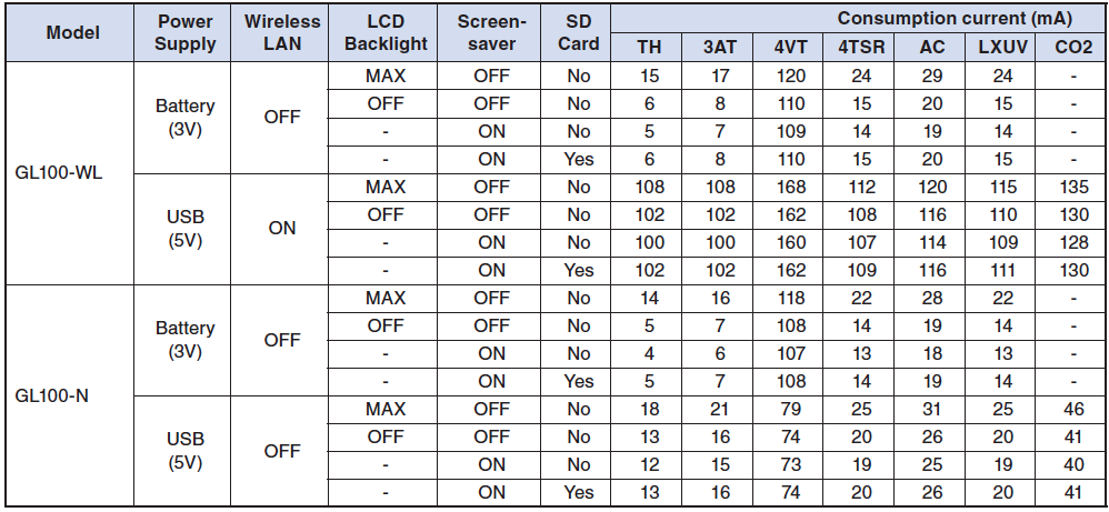
※ The above figures are average values for the combined package for both the main unit and the sensor.
※ Changes in sampling speed does not impact the overall current consumption.
※ Power consumption increases by approximately 20 mA when recording on the SD card.
※ CO2 sensor increases current consumption by about 500 mA on a regular basis (about 2 second intervals).
HOW MANY DAYS CAN THE DATA BE STORED IN THE INTERNAL MEMORY?
The number of days that data can be stored in the 4.9 MB of the internal memory is about 254 days with the nonvolatile memory.
※ This period of recording depends on the module type and channel count. 254 days is for the Temperature / Humidity Sensor (GS-TH) Recording temperature, humidity, dew point temperature, integrated temperature with sampling rate at 1 minute interval (when connected to a power supply).
Memory recording Tips
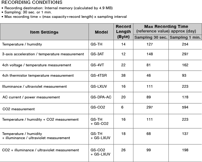
The recording time will vary depending on the memory capacity. Refer to the table below for recording time references.
Operating Condition
· Recording location: internal memory (approximately 4.9 MB)
. Sampling: 30 seconds or 1 minute
※Maximum recording time = (maximum capacity ÷ record length) × sampling interval
(1 KB = 1024 bytes)
| Setting Items | Models | Record length (Byte) | Max. Sampling 30 sec. |
Max. Sampling 1 min. |
|---|---|---|---|---|
| Temp. & Humidity | GS-TH | 14 | 127 | 254 |
| Acceleration & Temp. | GS-3AT | 12 | 148 | 297 |
| 4ch, Voltage or Temp | GS-4VT | 22 | 81 | 162 |
| 4ch, Temp. (Thermistor) | GS-4TSR | 38 | 46 | 93 |
| Illuminance & UV | GS-LXUV | 16 | 111 | 223 |
| Carbon dioxide (CO2) | GS-CO2 | 6 | 297 | 594 |
| AC Current & Power | GS-DPA-AC | 20 | 89 | 178 |
| Temp./Humidity + CO2 | GS-TH+GS-CO2 | 16 | 111 | 223 |
| Temp./Humidity + Illuminance/UV | GS-TH+GS-LXUV | 18 | 68 | 137 |
| CO2 + Illuminance/UV | GS-CO2+GS-LXUV | 26 | 99 | 198 |
HOW MANY DAYS CAN YOU RECORD CONTINUOUSLY ON 2GB SD CARD?
The number of days that can be recorded continuously on 2GB SD card is more than 2 years.
※ The number of days vary by the module type. The maximum file size is 1.9 GB.
WHAT IS THE OPERATING ENVIRONMENT OF THE MAIN UNIT?
Temperature: -10 to 50 ° C
Humidity: 80% RH or less (without condensation)
WHAT IS THE WATERPROOF AND DUSTPROOF MEASURE OF THE MAIN BODY?
The main body compact datalogger GL100 conforms to IP54 of the IEC standard, and it has a dustproof standard grade of 5 and waterproof standard grade of 4.
※ IP54 is for dust prevention that prevents the prescribed operation and safety of equipment and water splashing.
※ The spec is for operating on its own without any external power supply driven with AA alkaline battery and the connector cover is attached.
CAN I OUTPUT AN ALARM SIGNAL TO AN EXTERNAL LIGHT OR BUZZER?
An alarm signal can be put out from an isolated switching photo coupler on the GL100 main body using the alarm conditions set on the main GL100 options.
(Rating: 30 V, 50 mA (Power dissipation 150 mW))
With the wireless LAN-equipped model (GL100-WL), alarm information can also be sent by email to the specified email address.
HOW DO I CONNECT THE GL100 TO THE PC?
Both Wireless LAN model GL100-WL and non-wireless LAN model GL100-N can be connected to the PC using USB cable with Micro B-A type cable. Wireless LAN model GL100-WL can be connected to the PC with the wireless LAN, however only one PC and smart device is allowed to connect simultaneously over the wireless LAN.
Step1: Make sure you have downloaded the USB driver and the APS software >> CLICK TO DOWNLOAD
Step 2: Plug in your GL100 via USB into the computer. Open the GL100_240_840APS and hit the “Choose” option to get to the drop down menu. The easiest way to discover your device would be to “Search”. Once the IP address is found, hit connect. When the icon turns green, connection is established. You can hit the Close button at the bottom right hand corner to start the monitoring via wireless connection.


HOW CAN I RETRIEVE THE DATA?
Both the wireless LAN equipped, GL100-WL, and the one without wireless LAN, GL100-N, can connect to a PC by USB and files can be downloaded using the dedicated software or by transferring the data on the Micro SD card. Wireless LAN equipped models can connect to a PC via WLAN and the data can be retrieved with the APS software.
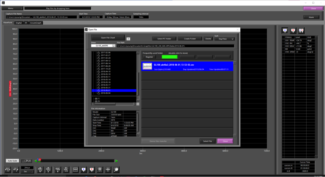
Step 1: When connected, hit the MENU for the drop-down option and select the open file option.

Step 2: From the new window, choose your file you wish to view and highlight the selection by clicking on it. Press select file on the bottom of the open file window. Your file will now open up in the software for playback and review.
WHAT ARE THE WIRELESS LAN STANDARDS AND COMMUNICATION DISTANCE OF THE GL100-WL?
Wireless LAN used on the GL100-WL is IEEE802.11b with 2.4 GHz band radio waves.
In an open environment without any obstacles, the communication distance is approximately 40 meters.
※Result depends on the site. Real time transfer rate: max ½ sec.
WHAT WIRELESS LAN MODES AND SECURITY SETTINGS CAN BE SET WITH THE GL100-WL?
The wireless LAN mode that can be set with GL100-WL can be set to Off, access point (GL100-WL acts as a hot spot), and station (GL100-WL will be set as a terminal on a network).
For security settings on the GL100-WL, you can set the GL100-WL to Auto (WPA / WPA 2 is automatically recognized), WEP, WPA, and WPA 2.
WHAT INFORMATION CAN I SEND WITH THE GL100-WL?
Email notices can be sent on alarm trigger, low battery status, signal strength low (RSSI), and disk full notice along with the real time data on the wireless notification.
WHAT IS THE RECOMMENDED SD CARD?
Our recommendation is Micro SDHC card that supports sleep mode. The format does have to SDHC.
Sample recommendation: TS4GUSDHC4 (Transcend)
Is it possible to measure both temperature and humidity at the same time?
The temperature and humidity sensor (GS-TH) connected to the main GL100 will both measure and record both temp and humidity.
Is it possible to measure room temperature at multiple places with certain accuracy?
Yes, it is.
By connecting the 4-ch thermistor terminal (GS-4 TSR) with the optional thermistor sensors, it is possible to measure at 0°C to 35°C with accuracy of ±0.2°C. The thermistor accuracy is ± 0.4 ° C (typical value).
I want to measure pulse, temperature and voltage at the same time, is it possible?
Yes, it is possible. You can measure temp, voltage, and pulse signals with the 4 ch. voltage / temperature module (GS-4VT). Any one of these channels can be set individually to measure temp (T/C type K or T), voltage (0 to 50V), or pulse.
Is it possible to measure AC current and power?
Yes, it is. The AC current sensors [50 A clamp (GS-AC 50 A), 100 A clamp (GS-AC 100 A), 200 A clamp (GS-AC 200 A)] combined with the AC current sensor adapter (GS-DPA-AC) will record AC current and power (W) signals on the GL100.
Please select the AC current sensor that matches the primary measurement current for your testing needs.
* For voltage and power factor input arbitrary value, power is calculated using the scaled values.
I want to measure temperature, humidity, illuminance levels at the same time, is it possible?
It is possible.
The combo package of the GS-TH sensor and the GS-LXUV sensor can measure all these measurements on the GL100-WL-LXUV-DPA-TH.
Is it possible to measure temperature, humidity, CO2 levels at the same time?
It is.
The combined package for the GL100-WL-CO2-DPA-TH offers measurements for both temp/humidity sensor (GS-TH) and the CO2 sensor (GS- CO2) through the GS dual port adapter (GS-DPA).
Is it possible to measure CO2 level and illuminance at the same time?
It is.
The combo package of the GL100-WL-DPA-LXUV-CO2 carries the CO2 sensor (GS-CO2) and the illuminance / UV sensor (GS-LXUV) along with the GS dual port adapter (GS-DPA) connected to the main body GL100.
Is it possible to measure acceleration and temperature at the same time?
It is.
with the GS-3AT 3 axis acceleration / temperature sensor carries both the acceleration (or vibration) and temperature recording sensor on the same unit. Products/GL100
I would like to extend the distance from the main unit to the sensor.
You can use the extension cable GS-EXC that extends the sensor connection to the GL100 by 1.5 meters (4.9ft).
What is the max AC current that can be measured?
Measurement up to 50 A, 100 A, 200 A is possible by selecting the appropriate AC current sensor (GS-AC50A, GS-AC100A, and GS-AC200A).
Is it possible to measure three-phase three-wire system?
It is. For 3-phase 3-wire system, measure with two AC current sensors mounted on AC current sensor adapter (GS-DPA-AC).
Refer to Installation Brief for GL100 Power Monitoring Solution in pdf (1.4MB) >> CLICK TO DOWNLOAD
What kind of thermocouples can be used with the 4 ch voltage / temperature terminal (GS-4 VT)?
K type and T type thermocouples are available with the GS-4VT voltage/temp module. The measurement temperature range of K type is -200 to 1370 ° C and the measurement temperature range of T type is -200 to 400 ° C.
What is the maximum voltage that 4ch voltage / temperature module (GS-4VT) can measure?
The maximum voltage that can be measured is 50 V (maximum input voltage: 60 V pp).
What is the resolution and accuracy of the voltage that can be measured with the 4 CH Voltage / Temperature module (GS-4 VT)?
The measured voltage accuracy is 0.15% of the set range.
The resolution is shown below in the table based on the set ranges
| Range | Resolution | Range | Resolution |
|---|---|---|---|
| 20mV | 0.001mV | 2V | 0.0001V |
| 50mV | 0.001mV | 5V | 0.001V |
| 100mV | 0.001mV | 10V | 0.001V |
| 200mV | 0.001mV | 20V | 0.001V |
| 500mV | 0.1mV | 50V | 0.01V |
| 1V | 0.0001V | 1-5V | 0.001V |
What is the input impedance of the 4-ch voltage / temperature terminal (GS-4VT)?
All channels are isolated inputs with 1 MΩ ± 5% impedance level.
What is the range of temperature and humidity for the temperature / humidity sensor (GS-TH)?
The temperature measurement range is -20°C to +85°C and the measured humidity range is 0.0 to 100.0% RH.
What is the resolution and accuracy of humidity and temperature on the GS-TH sensor?
The measure temperature accuracy is
-20 ≦ TS <0 ° C.: ± 0.8 ° C.
0 ≦ TS ≦ 60 ° C.: ± 0.5 ° C.
60 <TS ≦ 85 ° C: ± 0.8 ° C
Temperature resolution is 0.01 ° C.
The measure humidity accuracy is measured at 25 ° C.
0 ≦ RH <10: ± 10%
10 ≦ RH <20: ± 8%
20 ≦ RH ≦ 80: ± 5%
80 <RH ≦ 90: ± 8%
90 <RH ≦ 100: ± 10%
Humidity resolution is 0.1%.
What is the resolution and accuracy of the 4ch thermistor sensor (GS-4TSR)?
Measurement temperature accuracy of the main body is
-40 ≦ TS <0 ° C.: ± 0.7 ° C.
0 ≦ TS ≦ 35 ° C.: ± 0.2 ° C.
35 <TS ≦ 70 ° C: ± 0.4 ° C
70 <TS ≤ 120 ° C: ą1.0 ° C.
Thermistor accuracy: ± 0.4 ° C (typical value) GS-103AT-4P / GS-103JT-4P
Temperature resolution is 0.01 ° C.
What is the fastest sampling rate of three-axis acceleration / temperature sensor (GS-3AT)?
It is possible to sample from maximum 5 ms in memory mode and 500ms with the direct mode. Memory mode is when recording is set to the recording destination medium based on the selected sampling speed. Direct mode computes and displays subsampled data for each sampling setting.
You can also select one of the following calculations: contents, peak, average, and RMS.
(The subsampling interval is fixed at 5 ms for the direct mode)
CONNECTING GL100 TO GL240 AND GL840
Step 1: Hit Menu.
***Make sure you have Wireless Module Attached. (highlighted in yellow)

Step 2: Use arrow Key to go to WLAN

Step 3: Click on highlighted green box to get drop down Menu
Step 4: Select Access Point and hit okay. Then hit the Enter button on the Restart the wireless LAN(highlighted in Yellow) and wait for it to restart.

Step 5: Now, you will get a screen similar to the one above. Here is where you set your name and if you want, a password. The SSID Input (highlighted in red) is where you choose the name of the GL240/840 so you can select it from the GL100. Next you will select Encryption method (highlighted in Yellow), which is where you select how secure your password is, this will also bring up an extra column of where you can put in a password.
After these parameters have been set, Hit Apply settings (highlighted in Green) and we are now done with the GL240/840 for now and will now be grabbing the GL100.

Step 6: Now we are working from the GL100, when powered on, your start screen will look similar to this depending on the sensor connected. From here hit the MENU button highlighted in red.
Step 7: Now Hit the Left arrow Key to switch MENUs until you are at the I/F menu.

Step 8: You will want to set the WLAN mode (highlighted in red) to Station. Then Set your SSID and Security setting (highlighted in yellow) to the same as you set your GL240/840 too.
Step 9: After you have set everything up from step 8, press QUIT on your GL100 to return to the main screen. From here you should now see LAN (highlighted in red), this will indicate that you are now connected to the GL240/840. From here we now go back to where we left off on the GL240/840.

Step 10: Now that you are back to your screen you left off on the GL240/840, go down to the Wireless sensor settings (highlighted in red) and select it to get menu.

Step 11: From here select connection to On (highlighted in red). Then go over to search (highlighted in yellow) and it will search and find your GL100 sensor, from there select it. Then hit OK (highlighted in green). Now if you go to the AMP (highlighted in Blue) menu there will be one more step.

Step 12: Once back to the AMP MENU, you can toggle between displays, if you hit the DISP (highlighted in red) you will get a drop down menu to select. Once selected the input and sensor will change to the GL100. If you hit Quit after selecting you will get the screen similar to the two below.
INSTRUMENTS > FAQ > GL100