
FAQ > GL240
GL240
Connecting GL240 to GL840 > Click here
Maximum voltage measurement> Click here
Turn on pulse / logic> Click here
Adjust temperature to zero> Click here
Setting up GL240 with B568 WLAN as access point> Click here
Converting file GBD to CSV on GL240 > Click here
Adjusting scaling for sensor / transducer measurement on GL240> Click here
How to send an email when trigger / alarm is set off on GL240 > Click here
Saving and loading contain setting on GL240> Click here
Setting up alarm on GL Series > Click here
CONNECTING GL240 TO GL840 VIA USB
Step 1: Download and install both the USB driver and the APS software from our web site.
For GL240 Download Software >> Click Here
For GL840 Download Software >> Click here
Step 2: Onced you have downloaded and installed both items, proceed to opening the GL240/840 APS software. You will get this screen onced open and next you will click on the connect button on the top right hand corner of the APS software (highlighted in red).

Step 3: You will now get a pop up window and will see many options. You will most likely be connecting up one GL on your computer and select connect on the top Column (highlighted in blue). Select which GL you are connecting to the computer using the drop down menu (highlighted in red). Next make sure the USB ID numbers matches on your GL and APS Software. You can check this on your GL by hitting the MENU button on the actual device and scroll through the menu to the I/F tab. Here you will see the USB settings and your USB ID. Double check the USB ID with what’s on your APS (highlighted in yellow). Now that everything correlates with one another, choose the connect button located to the right of your USB ID number which was highlighted in yellow and then click the close buttons for your setting to take place and load the GL to the computer.
MAXIMUM VOLTAGE MEASUREMENT
GL240/GL840 Max Voltage is 110V; Can I measure higher voltages?
Yes, but only if you use a Voltage Attenuator. The Voltage going into the GL must remain less than or equal to 110V. The withstand voltage of the GL240/840 is 350V P-P for up to 1 minute. This means that the instrument can withstand up to 350V for up to 1 minute, but any time thereafter may cause the terminals to burn out. We recommend keeping the voltage levels within the recommended specification.
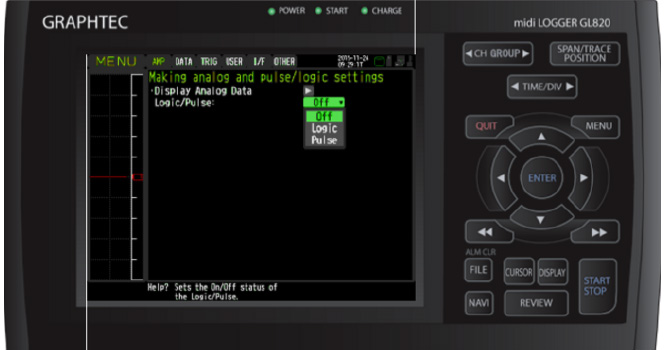
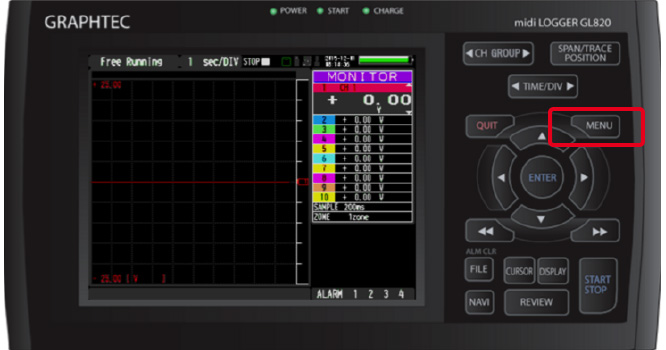
TURN ON PULSE / LOGIC
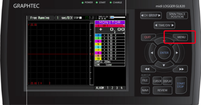
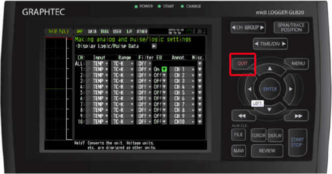
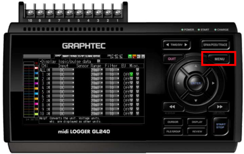
Step 1: From the main screen on your unit, hit the “MENU” button to proceed the menu screen.
Step 2: Once the “MENU” screen has come up, scroll down using the down arrow key.
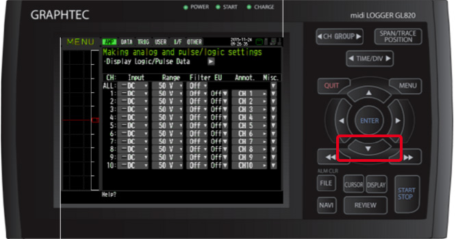
Step 3: Scroll down once until you reach the “Display Logic/Pulse Data” and hit the “ENTER” Button.
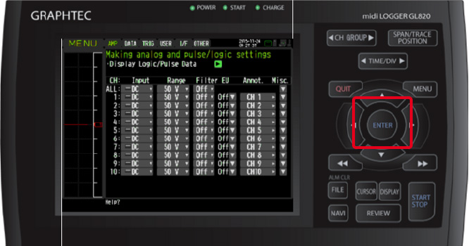
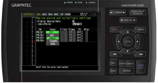
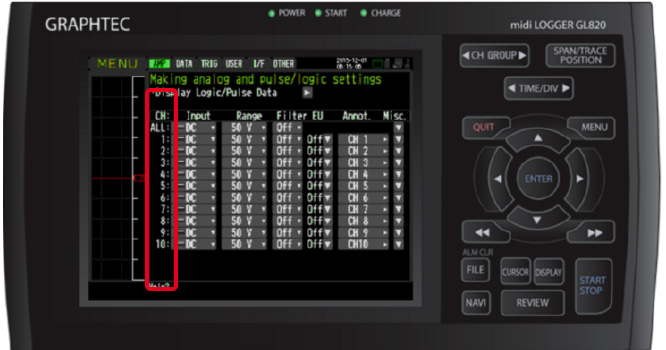
Step 4: Once at the “making analog and pulse/logic settings” Menu, on the Logic/Pulse option, choose which one you would like to use. Either Pulse or Logic.
Step 5: Now choose which Input you would like to use, you have 3 different options to choose from.
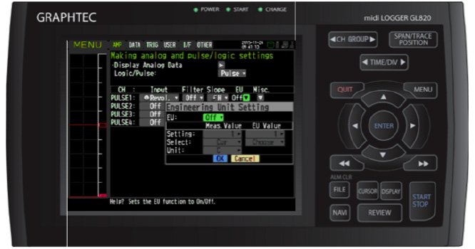
Step 6: You ca also use the Engineering scale to make sure the signal you have coming in is correct. When you are setting the high and lows for your pulse/ logic signal, the first column which says measured value will be your voltage range of the sensor that you are using. The second column, which is EU value will be the range at which your sensor can read (ex: 0 – 60 PSI).
Step 7: Once all of your values are set, you can hit QUIT on the GL to return to the main screen.
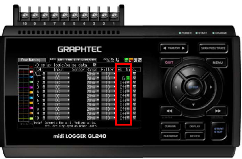
ADJUST TEMPERATURE TO ZERO
Step 1: From your GLXXX main screen hit the MENU button.
Step 2: When on the MENU screen, Scroll down to the channels you will be using to measure.
Step 3: Once you have picked which channel, scroll over to the right to the EU Column and click ENTER to bring the drop down MENU.
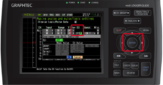
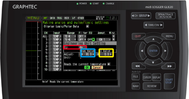
Step 4: Turn the EU Setting to on (highlighted in red). To set your adjustment you will use the adjust values. The Measured (highlighted in blue) will be what your Temperature is reading and your EU value (highlighted in yellow) will be what you want it adjusted to. SO if your temperature is off by 30 and you want to measure 0, then set the measured value to 30 and the EU value to 0. Once you values are set, click ok on the drop down menu to save settings.
Step 5: You can proceed with changing other channels to what you need or you can hit the QUIT button to exit back to the main screen.
SETTING UP GL240 WITH B568 WLAN AS ACCESS POINT
CONVERTING FILE GBD TO CSV ON GL240
Note: You can only convert from GBD to CSV, not the other way around. So it is best to save in GBD as you can convert to CSV at any time.
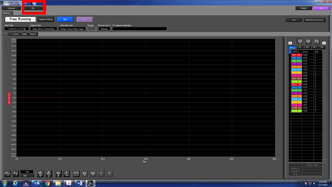
Step 1: Once you have opened the APS and connected the GL, you must press the File button located near the top left of the screen (highlighted in red).
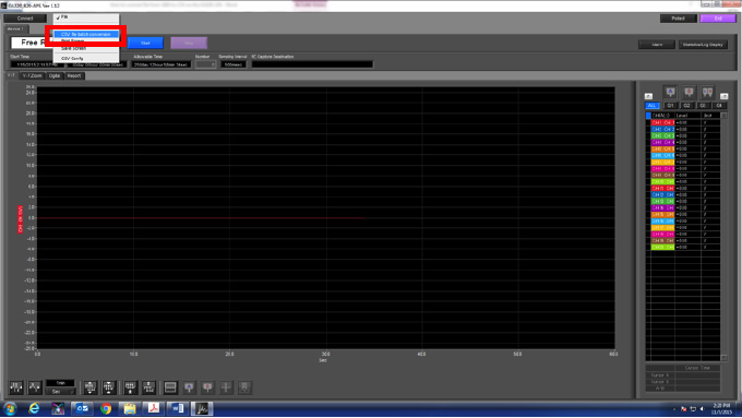
Step 2: After clicking the file option, a drop down menu will appear and you choose the option GBD file batch conversion (highlighted in red)
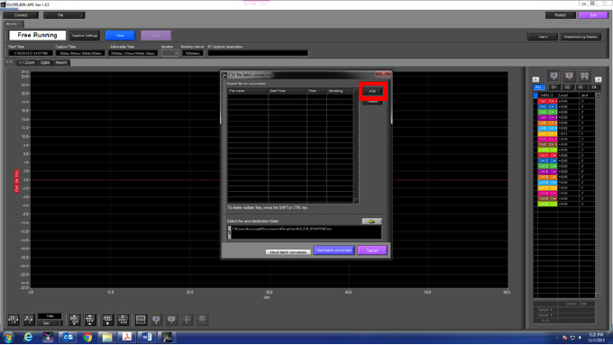
Step 3: A new menu will pop up now that you selected the file option. From here press the add button (highlighted in red). This menu is a batch menu where your added files that you want to convert will show.
Step 4: When the new window pops up, you will have options on the left hand side on choosing where you are importing the file from (highlighted in green). Your files will appear on the right of where you select the file. Here is where you will see the files that are in the location you are choosing from, this is where you select the file you want (highlighted in red).
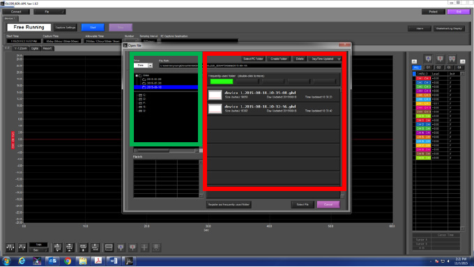
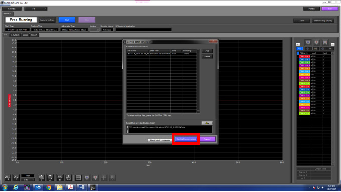
Step 5: After your file is selected, you will see what you chose pop up in the batch menu. From this point, you can either add more files to the batch or you can select start batch conversion (highlighted in red) which will convert the file you have selected
ADJUSTING SCALLING FOR SENSOR - TRANSDUCER MEASUREMENT ON GL240
STEP 1: Open up your GL unit and connect your GL to it by matching up the USB ID on the unit and the software.
STEP 2: Once connected, you will be directed towards the page you see above. From here click on the MENU button highlighted in red.
STEP 3: Once the settings window pops open, on the first tab which is the AMP Settings, turn on the scaling on the channels you would like to change (highlighted in red). Once turned on, the channels that have the scaling on will turn blue as shown above.
STEP 4: When a channel is turned on, a scaling window will pop open and from this window, you will set the scaling to your needs. If your GL is measuring off and you need to add .67 V to a channel then under the measured value on the left (highlighted in red) you would set the value of what you are measuring, such as from 0V to 2V. On the EU value (highlighted in blue), this is where you will set the offset or what you are scaling too. Because you want to add .67V, you will put the upper .67above 2 and same goes for the lower value as shown in the above picture. Select ok to save an exit out.
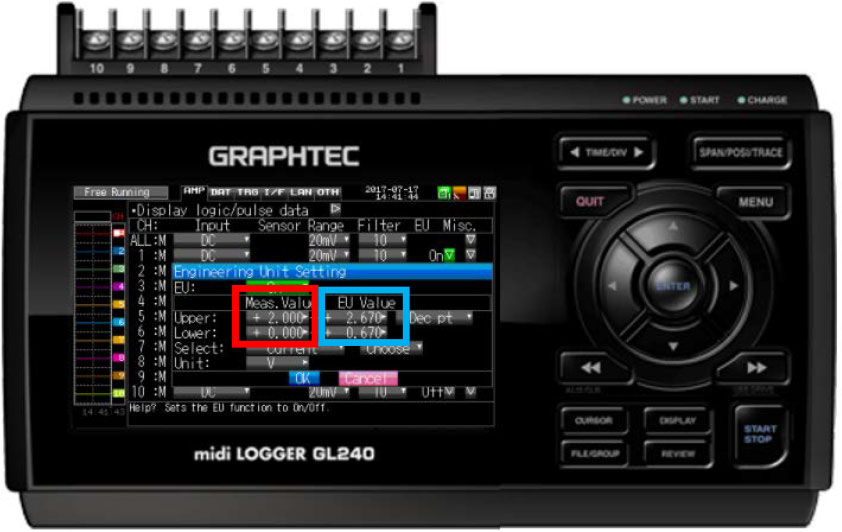
STEP 5: Once you have finished with your settings, you can click APPLY and then OK at the bottom left hand corner of the Settings window. You are now ready to start your adjusted measurements.
HOW TO SEND AN EMAIL WHEN TRIGGER / ALARM IS SET OFF ON GL240
NOTE: Make sure you have a wirelless B-568 attached and are already have your G240 connect to your network.
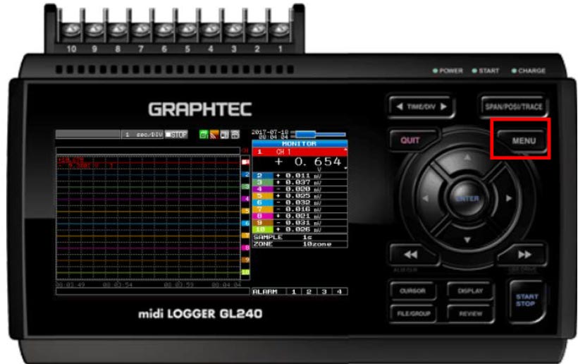
Step 1: Hit the MENU button (highlighted in red) to bring up the menu you see above.
STEP 2: Scroll over to the TRIG tab. On this menu tab you are able to set your alarm features. You can choose what type of trigger condition you want to have and the levels at which those would be activated. Pay attention when settings these as each channel is setup individually.
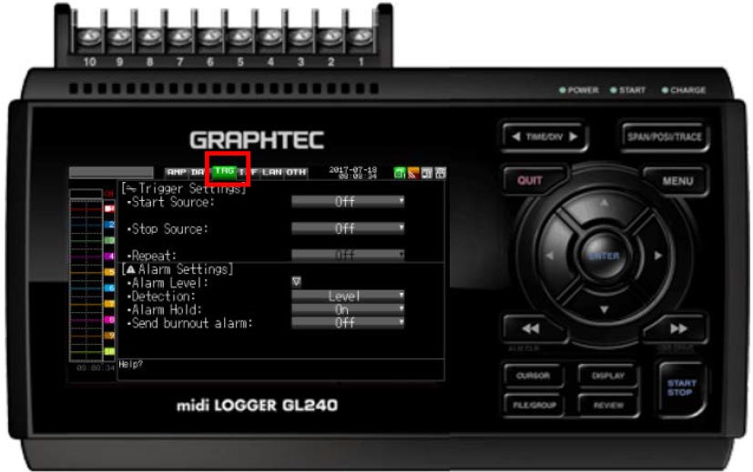
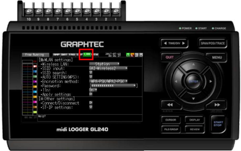
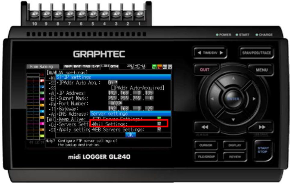
Step 3: After you have set you alarm/trigger setting to your needs, scroll over two tabs to the right to the LAN settings (highlighted in red).
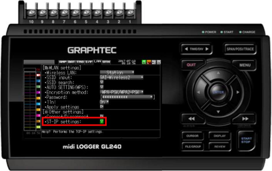
Step 4: Scroll down to the ST-IP settings and hit ENTER (highlighted in Red)
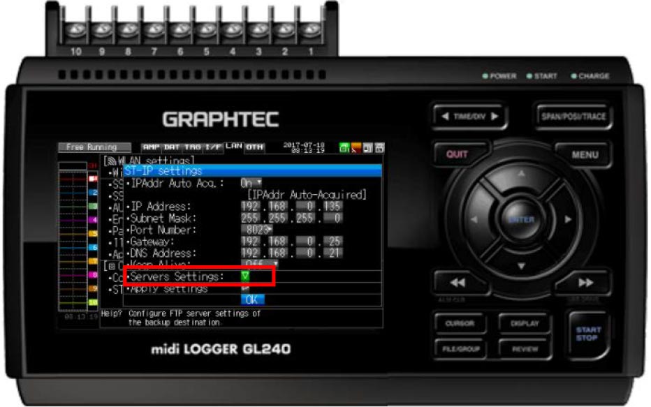
Step 5: Now Scroll down to the Servers Settings (highlighted in Red).
Step 6: From here scroll down and hit enter on Mail settings (highlighted in red)
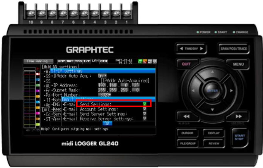
Step 7: Now, here is where you will be setting up all of your email settings. You will need to get in touch with your IT department for some of the information that will be needed. We will go through the first three Email Settings on here. Starting with the highlighted one Send Settings. After you perform these settings, you will hit okay to get back to the menu above and will proceed down the list until instructed.
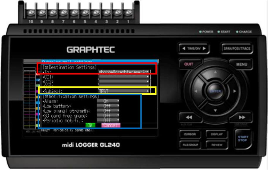
Step 8: Highlighted in red, is the destination settings where you will put who is receiving the email and there are 3 extra spots for other emails as well. Proceed to the Yellow highlighted box, and in here you will be Typing in your Subject. Next we move to the blue, these will be set a user discretion. Now Hit ok.
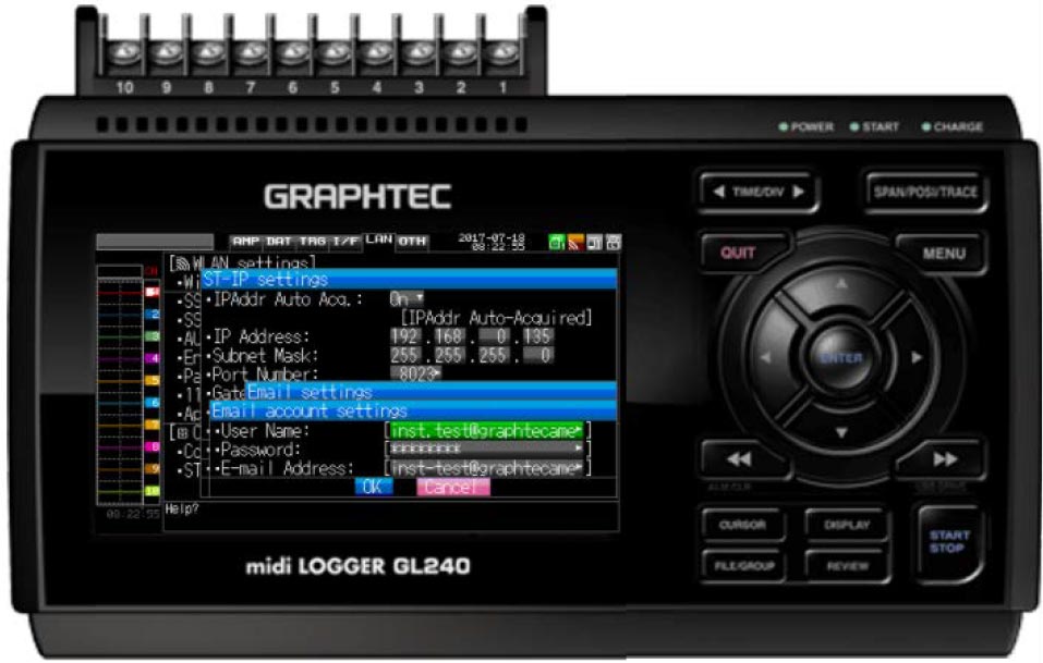
Step 9: Once you scroll down one to the Email Account settings, hit enter and you will get a screen above. Here you will enter the email address and password associated with the SMPT account. After your settings are set, hit ok and when back at email settings MENU scroll down one more to Email send server settings.
Step 10: In here, you will enter you SMPT server information which you can get from you IT department. Once your setting are done, you hit ok to apply and then make sure to hit apply on the ST-IP settings menu.
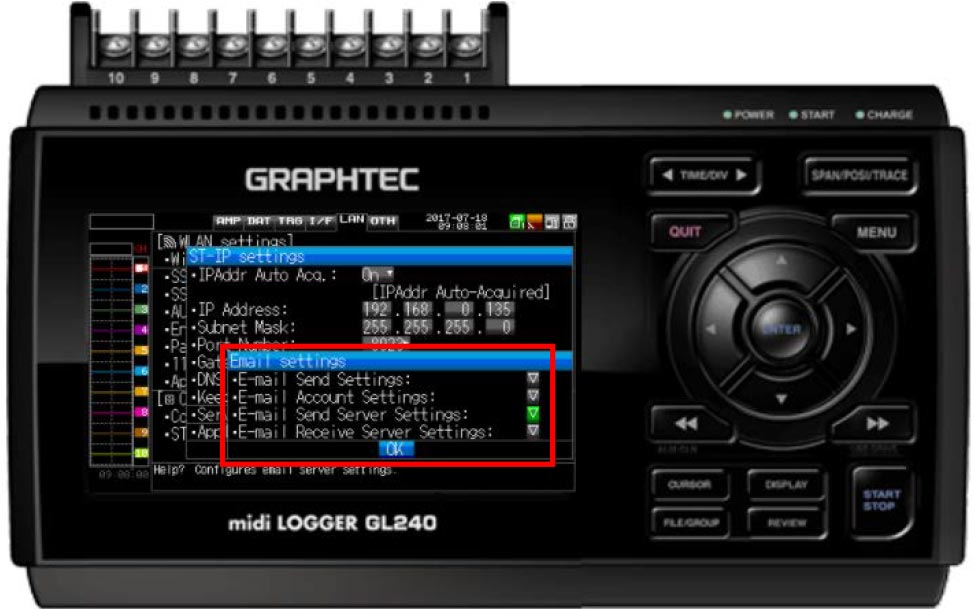
Step 11: Now you can record and if your settings get triggered, you will get an email sent to whichever email you set it up to.
SAVING AND LOADING CONDITION SETTING ON GL240
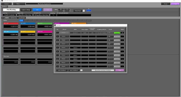
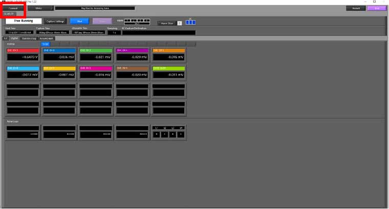
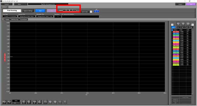
Step 1: First you must connect your GL to the APS software. Make sure that USB ID on both the software and GL match up. Once connect the connect button will turn green and you can close out of the connect menu.
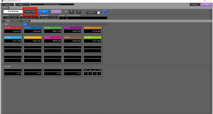
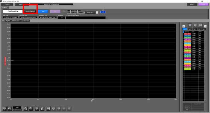
Step 2: Once you close out of the connect window, you will see a screen similar to the one above. Set the conditions you want by selecting the capture settings button highlighted in Red.
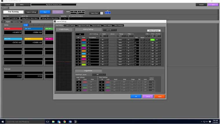
Step 3: When the Capture settings window pops up, you can set the conditions to whatever is needed. Once this is done, hit the APPLY button, then hit OK both are located at the bottom right of the Capture settings screen.
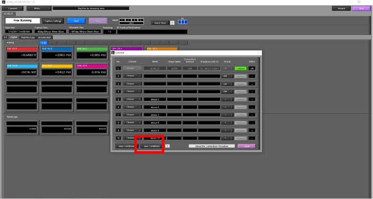
Step 4: Now that you have you conditions set to what you want to save, hit the Connect button highlighted in Red.
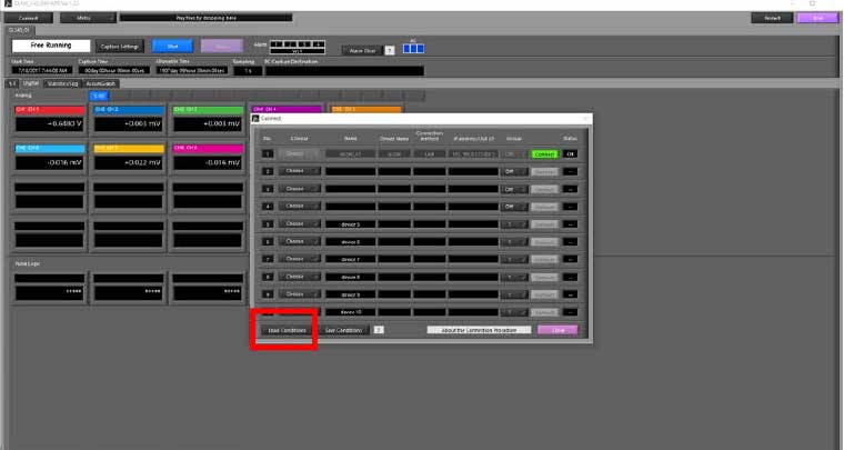
Step 5: When the connect menu pops up, hit the Saving Conditions Button highlighted in red.
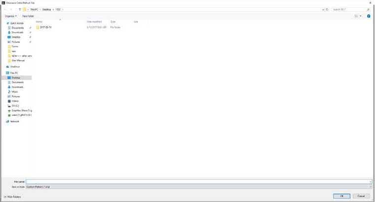
Step 6: After selecting the Saving Conditions button, a save screen will pop up. From here you can save it either in the computer or on an external drive by selecting the location. Once location is selected, choose a name for the file and click OK.
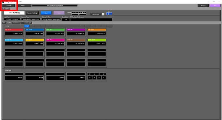
Step 7: Once you have saved the file, you will be redirected to the connect screen. From here you can close the MENU.

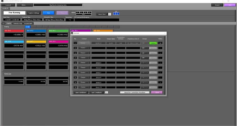
Step 8: Your condiotns are now saved and you can access them from any GL or APS software. To do so, from this main screen of the APS, click the connect button highlighted in red.
Step 9: On the connect MENU, hit the Loading Conditions Button highlighted in Red.
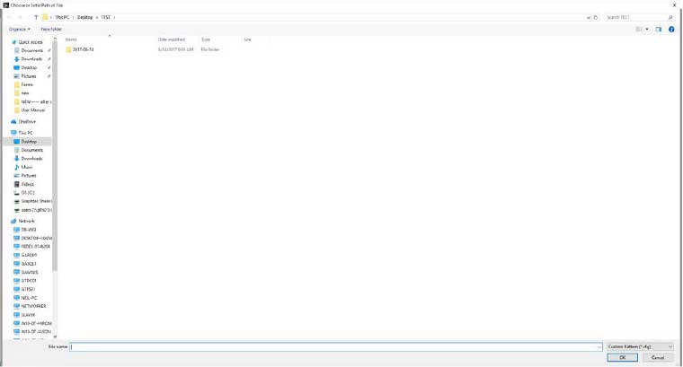
Step 10: You will ne directed to your Computers folder menu and from here you can locate where you saved yur conditons and load them.
Step 11: Once you have selected your file to load your conditions, you will be re directed back to the connect screen. From here you can close the connect screen.
Step 12: Your conditions are now loaded and you are ready to start recording.
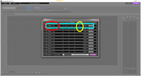
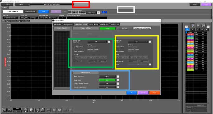
SETTING UP ALARM ON GL SERIES
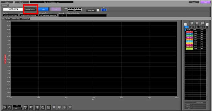
Step 1: Connect your GL to the APS software. Once connected, a screen similar to above will show. From here Click on the Capture Settings (highlighted in Red).
Step 2: When the Capture screen appears, clcik on the Trigger/Alarm setitngs tab(highlighted in red). From here all your alarm and trigger setting can be chosen.
Highlighted in white, is the schedule option, this will allow you to set your schedule based on either hour, day or month.
Highlighted in the green box is the Trigger start conditons, here you can set the trigger to star the recording or have an alarm happen when this trigger is met. Depending on what condition you choose, the different options in the highlighted green box will change.
Highlighted in the yellow box is the Trigger stop conditions. This is the same thing as the start, expcept for that it will stop the alarm/ recording for you.
Highlighted in the Blue box is your alarm settings. The alarm conditon will allow you to choose which alarms (1,2,3 or4) will go off for what which channel. IF you want your alarm to stay until the stop conditon is met, that when the alarm hold option would com in handy.
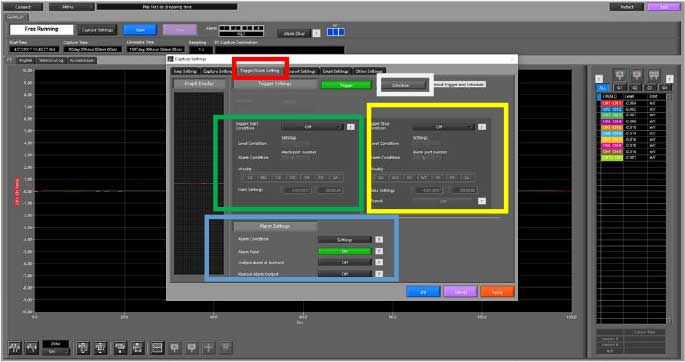
Step 3: Once your settings have been implemented, you will be able to see the alarms of either the bottom left of the GL unit or top middle left of the the APS (highlighted in red) when the condion is met.
SETTING UP ALARM ON GL840
Step 1: Connect your GL to the APS software. Once connected, a screen similar to above will show. From here Click on the Capture Settings(highlighted in Red).
Step 2: When the Capture screen appears, clcik on the Trigger/Alarm setitngs tab (highlighted in red). From here all your alarm and trigger setting can be chosen.
Highlighted in white, is the schedule option, this will allow you to set your schedule based on either hour, day or month.
Highlighted in the green box is the Trigger start conditons, here you can set the trigger to star the recording or have an alarm happen when this trigger is met. Depending on what condition you choose, the different options in the highlighted green box will change.
Highlighted in the yellow box is the Trigger stop conditons. This is the same thing as the start, expcept for that it will stop the alarm/ recording for you.
Highlighted in the Blue box is your alarm settings. The alarm conditon will allow you to choose which alarms (1,2,3 or4) will go off for what which channel. IF you want your alarm to stay until the stop conditon is met, that when the alarm hold option would com in handy.
Step 3: Once your settings have been implemented, you will be able to see the alarms of either the bottom left of the GL unit or top middle left of the the APS (highlighted in red) when the condion is met.
USB DRIVER MODE FOR GL240
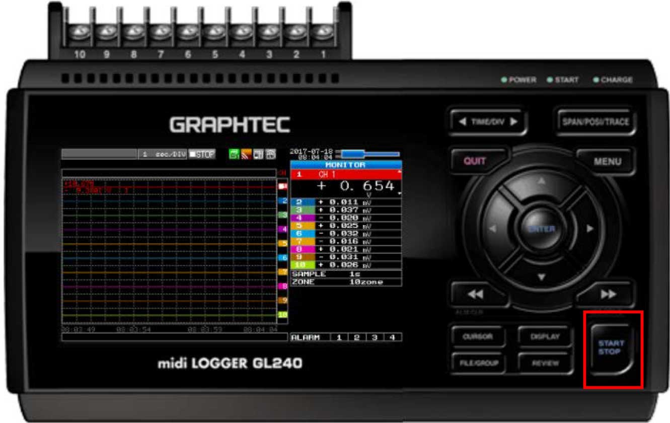
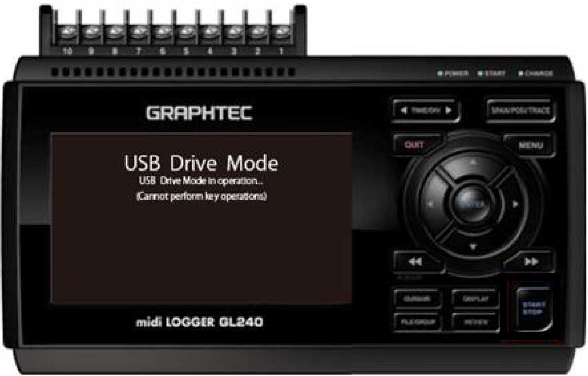
Step 1: While unit is powered off, press and hold the Start/Stop button (highlighted in Red) while powering up the unit. After the unit is done initializing, it will take you into USB driver mode. After the unit completes initializing the boot up, the unit will go into the USB drive mode.
Step 2: From here, with the USB cord plugged in, you can view your saved files on your computer as if it was a flash drive. When you’re done with file transfers, close your file explorer window, and you can power cycle the device to return to the main menu and start using the instrument in regular data logger mode.
INSTRUMENTS > FAQ > GL240